 |
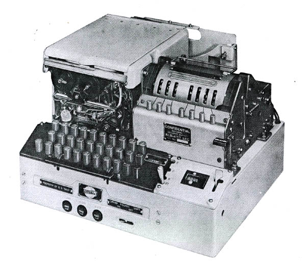
| This is the Navy version of the KL-47 which was designated as TSEC/KLB-47. (Photo courtesy NSA/National Cryptologic Museum) |
GENERALIn the 1960's, the intelligence community used the KL-47 as an off-line backup for forwarding critical information to national command authorities when a "covered" circuit was unavailable. This was usually due to poor radio frequency propagation causing synchronous crypto gear to lose synchronism. KAO.41C/TSEC) has the following interesting passage:
Per manual KAO41C/TSEC, the KL-7 is cryptologically inter communicable with the cipher machine KL-47, which is designed primarily for US Navy use. The KL-47 will encrypt not only lower case characters (letters) and numbers, but also will encrypt punctuation marks.
When it is necessary for stations using the KL-47 to communicate with stations using the KL-7, all punctuation marks will be spelled out, using authorized abbreviations, in order to avoid garbles.
Worldwide, the key and rotor combinations changed at 0000Z daily (HJ). A rotor basket, set up in advance, was quickly installed at changeover time to preclude any delays in decrypting critical intelligence. Several baskets containing different rotor sets and settings were kept close at hand in the event that a late arriving message used a key from the previous day.
One crypto expert did some additional research on the KL-7 and KL-47 machines. Here is what he found:
"First the types in order of development:1 AFSAM-7 = KL-7
2 AFSAM-47 = the troublemaker ( later in the text)
3 AFSAM-47B = KL-47First you have the KL-7, also referred to as ADONIS (US, UK, NATO) or POLLUX (UK, Canada). However ADONIS and POLLUX are actually not the names of the machines, but the names of the crypto principle (technically and procedures) they used for that machine. Before NSA, the KL-7 was named AFSAM-7 (AFSA Machine No 7), developed by the Armed Forces Security Agency (AFSA). This would become the new Combined Cipher Machine for use with the UK, Canada and NATO.
However, the US Navy decided to develop their own machine, not based on ADONIS or POLLUX, but on the BRUTUS principle. That one was however absolutely not compatible with the AFSAM-7 (later KL-7) and not as secure. They still insisted to develop that machine, and they called it the AFSAM-47.That AFSAM-47 was quite different from the AFSAM-7. It was based on the BRUTUS crypto principle, which used 26-pins rotors. However, the AFSAM-7 (later KL-7) used 36-pins rotors. Wheres the logic? There isnt any, apart from Army-Navy rivalry.
The US Navy eventually had to reverse course and redevelop the AFSAM-47 into the AFSAM-47B, which also applied the ADONIS principle with 36-pins rotors and fully compatible with the AFSAM-7. Hence the trouble with three machines, named AFSAM-7, AFSAM-47 (not compatible and obsolete) and AFSAM-47B
Once NSA was established, they finally decided to use a new nomenclature system and named the machines TSEC/KL-7 and TSEC/KL-47 (which is the compatible AFSAM-47B).
Now, what about the punctuation marks/uppercase system on the ? In the attached pdf document you find the uppercase systems used by machines types AFSAM-7 (KL-7)- and AFSAM-47 (KL-47). The AFSAM-47 (obsolete) used Extended Uppercase System with A-Z, 0-9, Space, LET, FIG, and - ( ) / : ? , . The AFSAM-7 (KL-7) used the Limited Uppercase System with A-Z, 0-9, SPACE, LET, FIG
In the attached document, referenced above, (see list at the bottom document) we see that the obsolete AFSAM-47 used A-Z, 0-9, SPACE, LET, FIG which are compatible, but it also used - ( ) / : ? , . and those are not compatible with the AFSAM-7 (KL-7).
The AFSAM-47B (your KL-47) is fully compatible with the KL-7. Therefore, the KL-47 at least took over the upper/lower case system A-Z, 0-9, SPACE, LET, FIG
It might be possible that the AFSAM-47B (your KL-47) also took over the - ( ) / : ? , . from the obsolete AFSAM-47, but I really doubt that, because if the KL-47 would use those punctuation, this would produce garbled text when received on a KL-7.
Conclusion, the KL-47 used A-Z, 0-9, SPACE, LET, FIG. "
|
| This is the Navy version of the KL-47 which was designated as TSEC/KLB-47. (Photo courtesy NSA/National Cryptologic Museum) |
Each KL-47 came with a set of 12 rotors packed in a storage box. Each rotor had 36 contact points. The eight rotors to be used for the daily setup would be specified by the daily keylist, with the remaining four being left in the box. The rotors werfe identical to those of the KL-7. Each rotor had a movable outside ring, which had to be rotated manually to a position also specified by the keylist that day for encryption and before being placed in the rotor basket. After setup, the basket was then placed in the machine and, as a way to verify accuracy, a 45 letter check was performed. The letter check was accomplished by typing a predetermined string of characters until the counter read "45". An innocuous stream like spaces, A's or some other specific character were used. The last ten letters on the sticky tape would then match the corresponding letters on the keylist if the setup was correct.The specific rotors and keylist used was sent to the distant end in the first group of the message (the system indicator). Specific settings for the movable rings on the rotors were encrypted on the PALLAS [1] keylist and then inserted as the second group of the message (the message indicator). Only for the off-line intelligence application was all of this set at 0000Z. Other messages were decrypted using rotors/settings communicated by the system and message indicators.
The quantities shown below were issued to the following services for service trails as authorized in a former SECRET document dated June 15, 1955
US Army - 4
USN - 2
USAF - None
NSA - 8 ( 4 of these were destined for trials in the UK)Unit cost in 1955 - $ 5,000
The last KL-47 (Navy Version) was taken out of US service in 1984 based on a note in the archives of the National Cryptologic Museum. In fact, the Navy version of the KL-47 was designated the TSEC/KLB-47.
DESCRIPTION
The KL-47, made by the Teletype Corporation, used rotors identical to those of the KL-7, however it was a slightly larger machine having a keyboard similar to the one used in the Teletype's ASR35 teleprinter. It also incorporated a paper tape reader and printer which typed characters on a gummed tape. There was a letter counter mounted above the keyboard.
The TSEC/KL-47 was comprised of:
KLB-47/TSEC base unit
KLA-47/TSEC stepping unit
KLK-47/TSEC rotor basketTo process a message, the rotors were set to the day's keylist. Then, using the keyboard, the operator would type the plain-text message. As the message was being typed, the KL-47 automatically encoded the message and produced an encrypted punched paper tape. When finished, the tape was given to the Comm Center where routing indicators, etc. were added and the message was sent.
TAPE PRINTER and PUNCH UNIT
The paper tape printer assembly and tape punch was nothing more than the standard Teletype Corp. typing reperforator. What is unique about this printer unit is the fact that it not only automatically generated 5 letter groups on encryption, but on decipherment, it printed 69 characters, then automatically performed the CR and the LF functions. There were no Carriage Return and Line Feed keys on the keyboard. The KLB-47 would actually ignore CR and LF characters and (usually) not garble.
There was also provision (not shown in the photos) for the connection of an external teletype so that hard copy could be made of either the encrypted or decrypted messages.
The KL-47 had problems handling the "stunt" characters ie Figs/Ltrs shift, upper case , so all traffic was composed the old way with all the figures and punctuation spelled out following the actual punctuation marks.
Because the keyboard was made by the Teletype Corp., it was a bit smoother than other machines like the KL-7. Once you got a rhythm going it was easy to type on and it was not necessary to pound the keyboard.
Displayed below are KL-47 components in their storage cases.
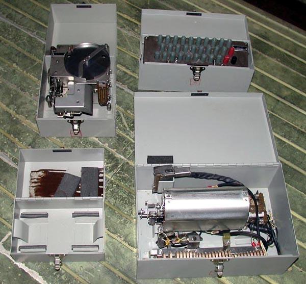 |
| These are the major subassemblies of the KL-47. (Photo by Don Robert House) |
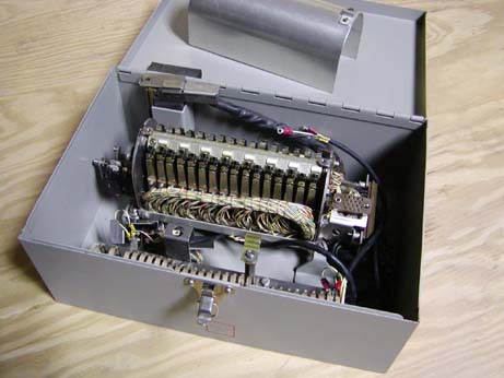
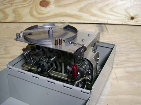
Assembly # 131817. The curved metal shield sitting in the carrying case lid normally covers and protects the switch assembly and is held in place by two screws. The socket at the right hand side of the rotor basket assembly is a rather standard Teletype Corp. receptacle which mated with a cable to the base unit. (Photo courtesy Combat Communications and Surveillance Museum)
Assembly # 131817. This view shows the individual microswitches for the stepping of the rotors and also the pushbuttons for setting the rotors to their initial positions, just like the KL-7 but in a different location. The KL-7 had the buttons for advancing the rotors at the bottom of the rotor crib, while the KL-47 had them to the rear of the rotor crib. The spring contacts at the front of the case mate with the keyboard. (Photo courtesy Combat Communications and Surveillance Museum)
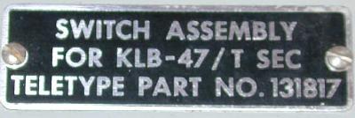
Nameplate for assembly #131817
Above and below: Front and rear views of the tape punch/printer. It did not just type the characters - it also generated a center or edge printed (user adjustable) 5 level, 11/16" standard Teletype tape. (Photo courtesy Combat Communications and Surveillance Museum) Keyboard .- top view (Photo courtesy Combat Communications and Surveillance Museum) Keyboard - bottom view. (Photo by Don Robert House)
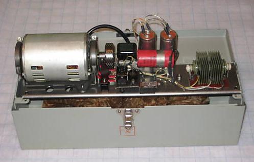 |
| Motor and power supply. (Photo courtesy E-bay) |
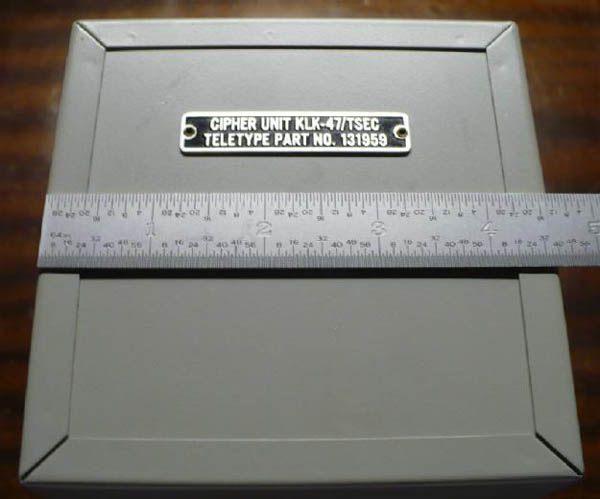 |
| Shown here is the label on a storage box for "CIPHER UNIT KLK-47/TSEC". The ends of the box measure 4 5/8" square and the box is 7 1/4" long. (It is presumed this box held the rotor basket and rotors) |
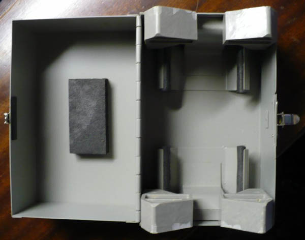 |
| Internal view of of the CIPHER UNIT box. There is a 1/2" thick
piece of resilient black foam attached to the inside top of the box.
Also, there are four resilient foam pieces attached to steel structures
which are spot-welded to the bottom of the box - the box contents
are cushioned by these foam pieces.
There are two gray plastic pieces held in place by the spot-welded steel structures. These plastic pieces limit the body length of whatever is stored in the box to 5 1/8". The plastic pieces are molded such that they allow for a shaft or spindle on both ends of the 'cipher unit' - that spindle can protrude 15/16" from each end and can be 15/15" in diameter. An educated guess says that the "CIPHER UNIT KLK-47/TSEC" is about 4 1/4" in diameter and about 5 1/8" long. |
| All photos and copy in this table by David Ross, N7EPI. |
SERVICE NOTESMaurice Cammack reflects on the KL-47. "I used this machine, along with an associated HL-1B, when I served as the only Cryptographer assigned to NSA Europe (NSAEUR), in the IG Farben Building in Frankfurt, Germany. I worked with the machine there for nearly 2 years, from July 1960 until June 1962.
We had several different organizational entities assigned to NSAEUR, and as might be expected, they did not always see eye-to-eye. I can still recall some of the "in fights" that went on among the movers and the shakers. Each group had their own privacy keylists, and in some cases, special editions of KL-47 rotors.
We also had a CIA "Liaison" Officer, a small technical staff, and representatives from the British GCHQ organization assigned to the unit.
I usually encrypted/decrypted the "privacy category" of messages for the individual elements which were then super-encrypted in on-line cryptographic systems operated by the USASA Europe Communications Unit in the Farben Building. As an aside, I never encrypted or decrypted any messages for the CIA Liaison Officer. When he had privacy messages to send or receive, I would set up the KL-47 with an appropriate keylist and then move to another part of the room.
I also do not remember ever sending any super encrypted messages for the GCHQ representatives. They undoubtedly had other channels of communications, but I never knew exactly what they were. It was a tremendous assignment for a young communicator, and I hated to return to the United States that summer.
I consider it one of the highlights of my military career since I had a unique opportunity to work with some very bright, dedicated professionals."
 |
 |
 |
 |
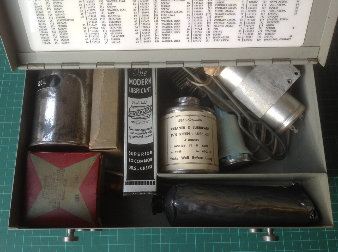 |
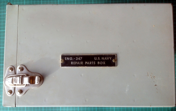
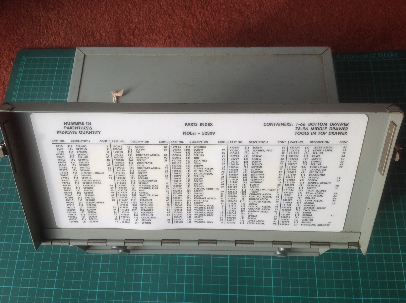
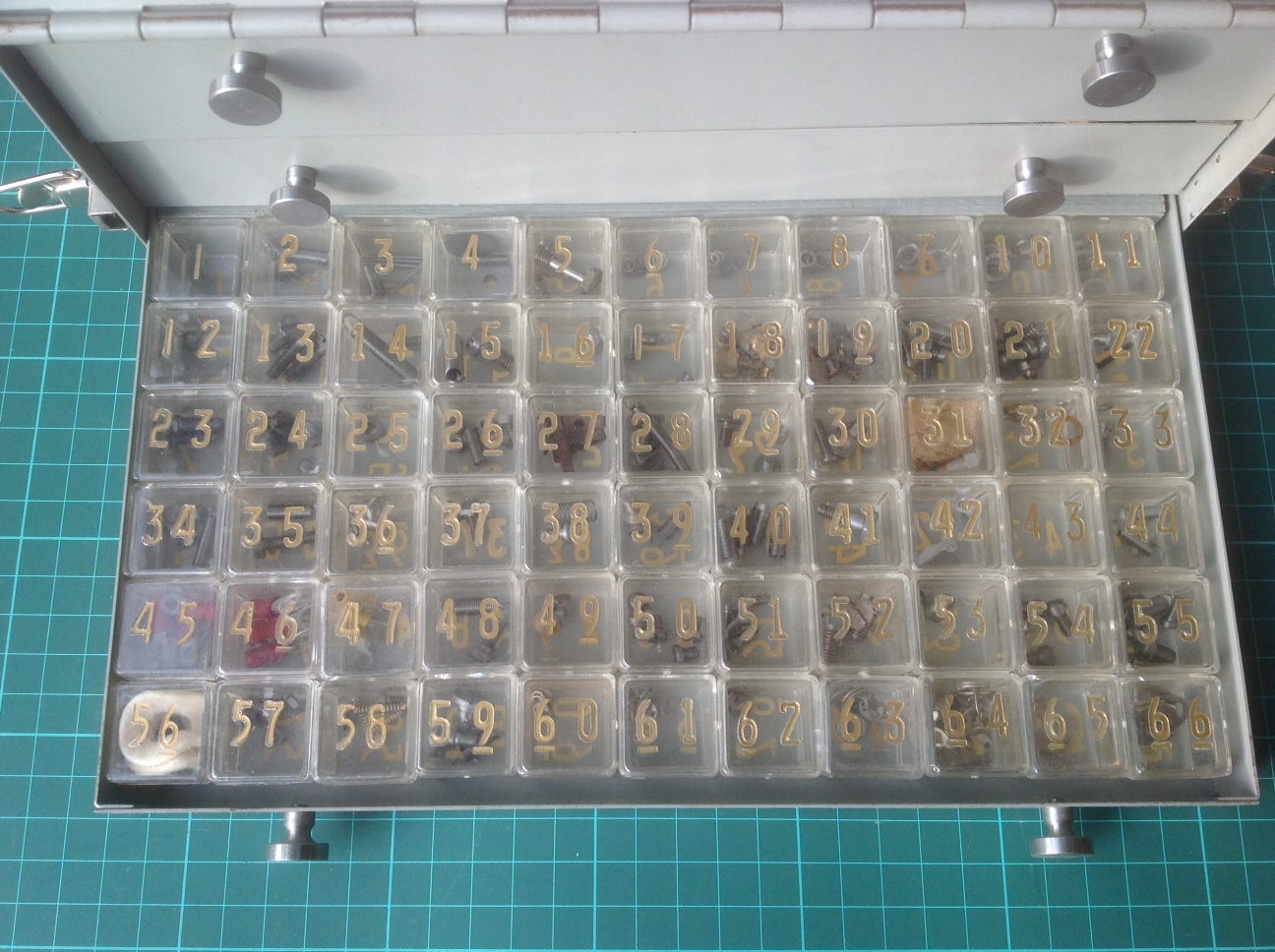
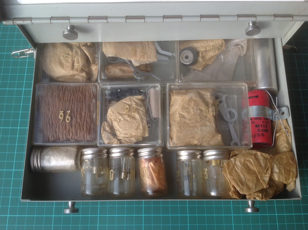
| All KL-47 spares photos in this table courtesy John Alexander. |
As a result of the capture of the USS Pueblo in 1968 by the North Koreans, the following cryptographic systems were compromised: KL-47, KW-7, KWR-37 and KG-14. An NSA report dated July 1969, details the cryptographic losses. A copy of this report can be found here.
Contributors and Credits:1) Glenn Eckfeld. E-mail: glenne(at)columbus.rr.com
2) George Mace <gmace8(at)comcast.net>
3) Warren Brader, Director Combat Communications and Surveillance Museum
4) Gregory W. Moore WA3IVX/ NNN0BVN. E-mail<gwmoore(at)moorefelines.com>
5) KLB-47 photo Cryptographic Equipment Planning and Reference Guide (CSP 6620A). Department of the Navy, Office of the Chief of Naval Operations, September 1962 via David Hamer/NCMF
6) David Ross <ross(at)hypertools.com>
7) Maurice Cammack <mecammack(at)telepak.net>
8) Don Robert House <k9tty(at)dls.net>
9) John Alexander <[jacrypto(at)gmail.com>
10) Doug Kerr <doug.kerr(at)att.net>
11) https://www.nsa.gov/public_info/_files/friedmanDocuments/ReportsandResearchNotes/
FOLDER_065/41701139074046.pdf
JAa 5/23