 |
| This KWR-37 example is held by the Communications and Electronics Museum in Kingston. (Photo by Jerry Proc) |
To many outsiders, cryptography is a fascinating subject and detailed material is not easily obtainable even after de-classification. At the turn of the twentieth century, messages containing confidential information were encrypted using code books and continued this way up to end of World War 1. In the 1920's, mechanical, rotor-based machines were developed in Europe and the United States for the purposes of encrypting commercial business traffic. By the late 30's, the German military had adapted a three rotor encryption machine that we now know as the Enigma. Rotor based machines continued to be refined until replaced by vacuum tube technology and finally, by the computer based technology of today. One of the most critical applications for secure communications was the military naval environment. In Canada, around 1962, the KWR-37 was introduced into the Royal Canadian Navy As the radio restoration volunteer for the ship, it was a strong curiosity towards crypto gear which provided the inspiration and initiative for the research and story which follows. The KWR-37 was a very advanced machine when first designed in the 1950's, but its service life was curtailed when security was compromised in the mid-1980's.
|
| This KWR-37 example is held by the Communications and Electronics Museum in Kingston. (Photo by Jerry Proc) |
All crypto gear fitted on Canadian ships in the 1950's and onwards was owned by the National Security Agency of the United States and was loaned to North Atlantic Treaty Organization member countries including Canada. This still holds true today and crypto gear used by all US government agencies is subject to the same strict regulations. Also included back then, was keying material, key lists, certain rotors, and key cards. This material came in a variety of editions depending upon the application. Examples of these crypto packages would be named CANUSEYESONLY (Canadian only), CANUKUS (Canada, UK, and USA), AUSCANUKUS (Australia, Canada, UK and US), NATO, ALLIED, and so on. Any edition with the designation of CANEYESONLY, would have been generated in Canada by the Communication Security Establishment. In 1962, aboard HMCS HAIDA, a pair of KWR-37's were fitted on steel racks, and a canvas cover blocked them from view as the crypto receivers were considered very top secret. The crude canvas cover, installed by the dockyard workers 35 years ago, can still be seen today.GENERAL DESCRIPTION
During World War 2, most 'low level' traffic from surface ships at sea was manually coded and decoded using code books. In the post war period, the amount of 'broadcast' traffic continued to increase to the point where it required some level of automation as manual decoding could not keep up with the volume of traffic. Automation made its appearance in the form of a teleprinter based receiving system. The sole purpose of the KWR-37 was to automatically decipher the encoded fleet broadcasts which was sent to military ships at sea and other applications where it was required to decode a steady stream of classified traffic. On the input side, the '37 was connected to the 60 milliamp current loop output of a frequency shift converter. The output side of the '37 was connected to a Teletype page printer.
The shore station started each day's broadcast at 0000 Zulu and transmitted without interruption for 23 hours and 55 minutes each day. On shore, the encryption device such as a KWT-37 was synchronized with a time signal station (CHU or WWV) and the originating station sent an automatic 'start' signal followed by a continuous stream of encrypted, non-repeating traffic throughout the day. The decoding 'key' which was similar to an IBM style punch card had a pattern of randomly punched holes, and had to be changed daily, prior to the start of the next day's broadcast. Encryption keys were changed by unlocking a front door on the KWR-37, removing the existing card, and installing the card that was designated for the next day. These cards were inserted behind a small door in the front of the KWR-37 using built-in, alignment pins. The door closed against a block of small, spring-loaded steel pins. Where a pin touched the paper card, no signal passed; where a pin poked through a hole in the card and touched a silver-plated metallic track, a circuit was made. Each card held enough keys to cover 14 years of usage before the key repeated itself. Used cards were destroyed on a periodic basis. In addition to the operational key cards, there were also cards used strictly for testing. Each card in the test deck, checked a different KWR-37 function. Two of the cards, produced a distinctive pattern of beeps to indicate proper operation and the technician had to listen attentively. With care, the test cards could last for years.
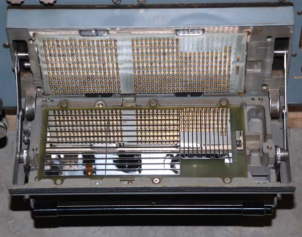 |
| KOI-7 card reader with door open. The highly reflective surfaces of the "return" conductor strips are very evident in this view. |
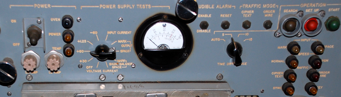 |
| Closeup of front panel controls and indicators. |
 |
| Meter dial detail: On the lower scale, note the 1.25 volt nominal filament voltage marking and the 1 volt low and 1.5 volt high margin levels. The 30 volt and 60 volt operating voltages on the other two scales have been aligned with the filament voltage nominal reading. |
 |
| Detail of receiver start time dial |
 |
|
|
 |
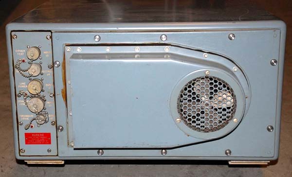
| Connections at rear of machine. |
| All photos in this table by Jerry Proc |
.jpg) |
| The special key to open the card cover is essentially three keys in one. That is best seen when one looks physically at the key. (Photo by Jerry Proc) |
John Dill of Kingsville Texas, was a crypto mechanic in the USN in the 1960's and 70's, and kindly documented his experiences with the KWR-37. "The holes in the punched cards directed the key stream to a series of bistable multivibrators (flip-flops) which were wired on thirteen printed circuit boards located on the left side of the machine when one opened the equipment drawer. All the flip-flops plugged into a motherboard which was positioned horizontally. The active devices in these circuits were sub-miniature, type 6088 sharp cutoff pentodes with wire leads and they were made by Raytheon or General Electric. These tubes were .38 inch in diameter and 1.5 inches long and anchored by metal clips on each circuit board. The 6088 pentode was also known as type CK522AX. Depending on circuit design, the 6088 could be driven to produce as much as 10.5 mw of power at the high end or as little as 1.2 mw at the low end! One multivibrator stage consisted of two 6088 pentodes for the flip-flop and one 6418 sub-miniature pentode amplifier, a vacuum tube originally designed for late generation tube computers. All stages had to be perfectly balanced, hence the use of resistors with 1% tolerance. Typically, the pentodes ran at 67.5 volts B+ and the triodes at 100 volts. There were four flip-flops per board and the entire unit contained approximately 500 tubes!Mechanically, the '37 was around 22 inches wide, 24 inches deep and 10 inches high with a case finished in navy cabinet grey. It could either be rack mounted or positioned on a equipment shelf. With a weight approaching 100 pounds, it was definitely a two man lift when being installed. At the rear of the unit there was only three sets of connections: current loop in, current loop out and power.
OPERATION
Transmissions began at 0000Z and continued without pause or repetition for 23 hours, 55 minutes each day. Whether any messages were being sent or not, the 'customers' KWR-37's were on-line, in sync and receiving the transmitted key stream. In the event of a power loss or if the unit went out of sync, the operator would have to initiate a restart. When the sending station stopped transmitting, all receiving units worldwide would be prepared to receive transmissions for the next day. If radio conditions were normal, the transmitting station's Auto Start signal would automatically start the machine. If Auto Start was missed due to atmospherics, the operator had to late start the unit. This procedure is discussed further in the text.
On the front panel of the unit, there was a control composed of two concentric dials; the outer for hours and the inner one for minutes. Above that, were three miniature switches marked Start, Reset and Sync. Two small, orange lamps tagged Mark and Space flashed alternately in time with the incoming signal. Re-synchronization of the KWR-37 required that the machine be reset, then run it forward in time at high speed to catch up to, then slightly pass, the transmitting station's key stream. The operator would set the Hours/Minutes dials to the difference between 0000Z and the current Zulu time. The Hours dial was marked in 1 hour increments up to 23. Similarly, the Minutes dial was marked in 5 minute increments up to 55. The Reset switch would then be pressed. This would reset the flip-flops in the Key Generator and the Internal Clock and ensure that all these circuits started up from a desired, known, pre-set value. Internally, the reset signal was routed to the flip-flop stages through the Key Card, thus changing the initial 'set' state of the Key Generator. Pressing the Start switch would enable and start the clock which began to drive the flip-flop stages thus producing the key stream. Activating the Sync switch would give approximately 15 seconds worth of high clock speed, akin to a fast forward function.
If for example, the KWR-37 had dropped off-line at 14 hours into the broadcast day due to loss of ships mains power, and restoral took 15 minutes, the operator would set 14 hours, 15 minutes on the dials and hit the Start button. The machine would run in high speed for several minutes until the clock had advanced the key stream 14 hours and 15 minutes, at which time it would drop back down to normal speed and start searching for sync. This process forced the KWR-37 in constantly comparing it's own internal timing to that which was being sent on the broadcast. If a clock comparison was unsuccessful, the clock would delete a pulse, effectively dropping it back in time by a small amount. Each time this pulse deletion occurred, an audible beep was sounded through a panel mounted speaker. As the beep rate slowed, it told the operator that synchronization was approaching. After several seconds of silence the Sync light would illuminate and the teleprinter (ie Teletype machine) attached to the '37 would start printing. The search for synchronization occasionally required the flipping the "polarity" switch on the front panel.
If the search for synchronization ran over several minutes duration, the '37 would alarm again with a steady, irritating, much-hated tone from the speaker along with the dreaded red Alarm light. Standard procedure called for resetting the machine and trying again. Since no two KWR-37's were exactly alike, the presence of the alarm did not mean that the machine stopped searching for sync. The alarm simply meant that the allotted amount of time had elapsed, during which, synchronization should have been attained. In many cases, the '37 achieved sync with the alarm sounding and the SYNC light on. At this moment, the operator would silence the speaker and everything would run normally. This was the official procedure for achieving synchronization.
In practice, however, it was an entirely different world. An operator would generally attempt the formal procedure. If this did not achieve results, a whole series of 'homebrew' remedies could be applied. Among these miracle cures for lack of sync were:
a) Pounding the front panel briskly just prior to pressing the START switch.
b) Opening the equipment drawer and hitting the tops of the circuit boards with some hard object such as a mallet or cleaning brush.
c) Opening the front door; removing the key card and cleaning the conductive tracks in the rear of the front door with a rubber eraser. This practice removed the plated silver on the tracks and was frowned upon.
d) Cleaning the conductive tracks with Teletype paper or paper money. Since Teletype paper contained trace amounts of oil to assist with lubrication, this practice was highly discouraged.
e) Rapid and vigorous spinning of the time-delay dials, followed by many shots on the RESET button.
f) Uttering foul, abusive language at the machine in order to let it know who was in charge!
John Clingman, an Electronics Technician in US Navy from 1969-1973, adds this unofficial technique to tame the machine when it was misbehaving. " I was not trained on crypto, but I talked with the crypto ETs and helped them with some peripheral maintenance. During that time, only ETs or RMs who were obligated for at least 6 years, were trained in the (relatively long) crypto equipment classes.
The rubber-hammer love taps to shake out the bugs in the KWR-37 is an interesting method of troubleshooting and repair. This was probably hard on the tubes, but vibrations form the firing of the ship's guns were pretty rough.
Our KWR-37 tech let me in on a technique that was sometimes used, and definitely not officially recommended. When many resynchs had been attempted (and failed), and the C.O. was applying pressure to get his Fleet Broadcast, sometimes the tech would risk a little increase in the filament voltage (above nominal.) This could result in getting the unit back in synch. Of course it weakened the tubes even faster. After a day or two, the slightly elevated filament voltage no longer did the trick. Another tweak and maybe it would work for another watch. Eventually, the weak tubes were beyond help and the formerly good tubes were also ruined or degraded. With large numbers of flaky tubes, it was nearly impossible to troubleshoot the unit. A full set of known good boards was required for a very time-consuming repair, swapping one sick board at a time into an operational receiver. A ship did not have that many spare cards, and would not have enough tubes to replace all the duds. A trip to the crypto shop on a tender or a shore base was needed. The Captain could be pretty cranky about a delayed deployment when a receiver was away at the shop."
Michael Deckard relates his experiences with the KWR-37.
"Our biggest problem was the Russian/Chinese interference that was intentionally jamming the time signals station WWV. Depending on where we were and the time of day, we could not always get a solid time-tic to properly get the KWR-37 to sync up The jammers could not jam all the frequencies so sometimes we got lucky. Often the Quartermasters Chelsea clocks were not accurate enough so a Bulova ACCUTRON watch came to the rescue! All the RMs and ETs chipped in to buy one. We had the Machinists fabricate an alloy block and mounted it to the KWR-37 rack. Now, all we left with was the Fleet Broadcast reception and the usual KWR internal issues."
MAINTENANCE
The KWR-37 originally designed in the 1950's was very tired and well past it's design life in 1968. It did not improve with age. Many technicians only had a modicum of training in the art of soldering. For the '37 family, this was a disaster as the most frequently performed corrective maintenance involved the replacement of wire lead vacuum tubes. One can only imagine the damage that was done to the printed circuit boards after 20 years of mediocre maintenance. To ensure the highest reliability, crypto mechanics tried to turn out a machine capable of operating normally with only 1 volt of filament voltage to all the 6088 pentodes. The standard setting was 1.25 volts and was indicated by a front panel meter. Each pentode had a filament draw of 20 ma. If the unit ran properly at a reduced filament voltage, that meant that the tubes had strong emission and the unit would run reliably. As emission decreased, the operator could increment the filament voltage to restore normal operation. When the machine became unreliable at a setting of 1.25 volts, it was turned back to the maintenance depot. Checking for operation at a reduced filament voltage became known as 'margining'. The 6418 pentodes which used indirectly heated 6.3 volt filaments were not margined.
Later and unofficially, an extender board was developed which allowed individual circuit boards to be margined. Once each board ran reliably at 1 volt filament voltage, the filament supply to the entire machine was reduced. If it worked, it was considered ready for use. Testing each board individually improved the quality of the troubleshooting process. The majority of maintenance problems in the '37 originated in three areas of the machine: the 'S' circuit cards, (the ones containing the key stream flip-flops); the 'T' cards which combined the 'S' card outputs and the 'U' or alarm cards. Next, were the cards which allowed the '37 to run at high speed. The modified card extender was invaluable in finding these circuit faults and eventually won official approval. A maintenance bulletin was circulated among all KWR-37 holders documenting the modified extender, the construction details and stock numbers of the parts required".
John goes on to comment about his worst KWR-37 repair job. "A navy technician had the '37 drawer open for maintenance. Innocently, a brand new Ensign, who was the ships Communications Officer noticed the activity and came over for a look. He must have been having a hard time at sea because of the large bottle of Maalox (stomach antacid) in his shirt pocket. As the Ensign leaned over to peek at the '37, the bottle fell out and broke on the top edge of the equipment drawer. Needless to say, the Maalox spilled throughout the machine and a large blue flash ensued as the power supply shorted out. Flames and smoke began issuing from the drawer. The tech had been sitting on the deck in front of the '37 cross-legged with his legs underneath the extended drawer. His burning trousers were quickly extinguished by the remainder of the Maalox running out of the equipment. In his haste to escape, the tech placed his full weight on the card rack and broke the motherboard in several places. The '37 was eventually repaired but the cost to repair, likely exceeded the value of the machine".
CONCLUSION
During it's service life, the security of the KWR-37 system was essentially compromised from 1968 to 1985. When the USS Pueblo was captured in 1968, the north Koreans acquired fully working KWR-37's along with active key cards. Naturally, there was a mad scramble to quickly change all of the cards held by KWR-37 'customers' all over the world. In the mid 1980's, it was discovered that the infamous 'Walker spy ring' was selling active key lists (ie the actual IBM style punched cards) to the Communists. It must be assumed that this activity had trasnspired as early as 1968. Once again, the key lists had to be quickly changed. It's important to note that simply possessing a machine was insufficient to copy the traffic in the short term. Any adversary had to be in possession of the active key lists in order to immediately decode any traffic. By the early 1990's, any remaining KWR-37 crypto receivers were taken out of service and destroyed. This sounds like a sad ending, but such is life in the world of cryptography.
As a result of the capture of the USS Pueblo in 1968 by the North Koreans, the following cryptographic systems were compromised: KL-47, KW-7, and KG-14 along with the KWR-37. An NSA report dated July 1969, details the cryptographic losses. A copy of this report can be found here.
I extend my sincere thanks to John Dill of Kingsville Texas for providing much of the source material which made this article possible. Additional information was also contributed by Gregory McLean of Abbotsford, British Columbia and Cdr. Bob Willson, RCN (Ret'd) of Toronto, Ontario.
SPECIFICATIONS:
Keying method: Punched keycards.
Input: Encrypted teletype.
Output: Plain text teletype.
Speed: 50+ wpm.
Application: Strategic and tactical environments.
Note: Generally used aboard ships.
In this view of the chassis, all the circuits cards and power supply tubes are missing as part of the "sanitization" process before crypto equipment can be released into civilian hands.
 |
| This unclassified VV card for the KWR-37 illustrates circuit design
using sub-miniature tubes.
On this card, there are three sub-miniature tubes, namely, RAYTHEON CE93258 (JAN6088) pentodes. Also, there are six sub-miniature tubes RAYTHEON CE93257 (JAN6418) pentodes. The following semiconductors are also in evidence: 2x 1N1518, 1x 2N43 and 2x 2N534 (Photo by Klaus Kopacz DC8HL) |
 |
| This auxiliary card plugged into a dummy slot in the KWR-37. Besides holding a cache of spare fuses, it also carried a "tuning wand" (blue item), The clamp held a small standard screwdriver which is missing. (Photo by John Dill) |
KWR-37 PARTS SECTION
 |
| This is the type of pin used in a number of card readers including the KG-13, KG-14, KWR-37 and KW-26 machines to name a few. The protrusion at the left is spring loaded. The connecting wire is soldered to the right side. Pin sample provided by Jerry Myers. (Image by Jerry Proc) |
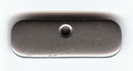 |
| This is one of the four special nuts used to secure the cardreader contact board. Nut sample provided by Jerry Myers. (Photo by Jerry Proc) |
TUBES USED IN THE KWR-37 6088 TUBE CHARACTERISTICS
Type: Sub-minature power pentode
Power Dissipation : 10.5 mw
Filament Voltage : 1.25 VDC +/- 20%
Filament Current : 20 ma
Plate Voltage : 67.5 volts max
45 volts typical
Cathode Current :1.5 ma max.
675 µa typ.
Bulb diameter : .385 in. max.
Bulb height : 1.5 in.
Wire lead length : 1.5 in
Envelope type : T2X3
First introduced in : 1951
The red dot denotes pin 1Reference: Tung-Sol Tube Manual, 1960

6088 Basing diagram.6418 TUBE CHARACTERISTICS
Type: Sub-minature pentode, computer rated
Filament Voltage : 1.25 volts
Filament Current : 10ma
Plate Voltage : 22.5 VDC
Envelope type : T2
First introduced in : 1957
Basing Diagram
During the era of the electo-mechanical crypto machine, Greg Moore would like to nominate one essential tool which would make most machines behave, if for just a while. That tool was the good old fashioned rubber mallet. Virtually any malfunction (real, imagined, or one of the evil idiosyncrasies which lurk in the heart of any good crypto machine) could usually be cured by a reasonable amount of whacks, applied over the card reader, the plugboard, or to any exposed part of the unit as most problems were caused by bad connections, an intermittent short in a tube, which could be "shocked back" to life. Please note, this was NOT in any way shape or form, OFFICIAL maintenance procedure, but after the 10th or so crash at 0300, one developed a hearty sense of animosity toward the darn alarm sounding. With missed traffic, one would do just about anything to get the equipment operating normally. The rubber mallet did not leave marks as did the otherwise useful Zippo lighter which could be extremely embarrassing during inspections by the Commo Officer.Greg Moore, former RM1, USN now WA3IVX
**********
On 28 May 1985, John Anthony Walker and his son, Michael Lance Walker were indicted by a Federal grand jury in Baltimore, Maryland on six counts of espionage. John A. Walker, a retired Navy warrant officer who had held a TOP SECRET crypto clearance, was charged with having sold classified material to Soviet agents for the past 18 years. During his military career, Walker made some investments in which he lost money. To make up for his losses, in late 1968 at the age of 30, Walker went to the Soviet Embassy in Washington, D.C., and offered his services for purposes of espionage. He compromised key cards used for enciphering messages and also provided information on the encryption devices themselves. At least a million classified messages of the military services and U.S. intelligence agencies were compromised by Walker. A Soviet defector said the KGB considered this the most important operation in its history. Michael L. Walker, a petty officer assigned to the USS Nimitz, was accused of providing classified Navy documents to his father for sale to the Soviets. Fifteen pounds of classified material were in his possession at the time of his arrest on the Nimitz. On 28 October 1987, both John and Michael Walker pleaded guilty to espionage under a plea agreement. On 6 November 1986, John Walker was sentenced to two life terms plus 10 years to be served concurrently. Michael was sentenced to 25 years. John Walker's arrest was the result of an FBI tip from his former wife.
Contributors and Credits: 1) Jerry Myers <jerry1joan(at)aol.com>
2) 6088 tube image courtesy http://townsendtubeworks.com/6088.htm
3) Communications and Electronics Museum, Kingston, Ontario
4) John Clingman <john11124(at)gmail.com>
5) Klaus Kopacz DC8HL <ibk_mail(at)gmx.de>
6) Gary Sponagle <g.sponagle(at)ns.sympatico.ca>
7) John Dill <jdill1927(at)mediacombb.net>
8) Michael Deckard <polyomnia(at)yahoo.com>
May 19/23


