 |
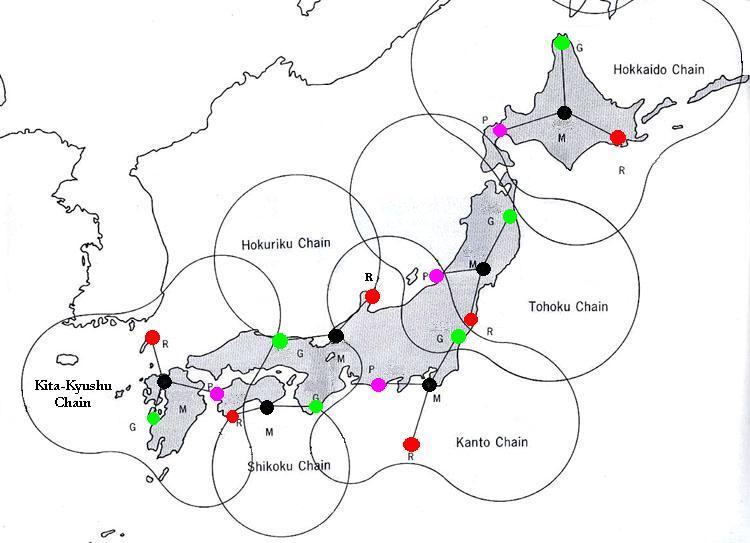
| This was the final Decca configuration for Japan showing the approximate coverage area. (Graphic courtesy Sena Company Ltd., Tokyo, Japan. Enhanced by Jerry Proc) |
DECCA JAPAN
|
| This was the final Decca configuration for Japan showing the approximate coverage area. (Graphic courtesy Sena Company Ltd., Tokyo, Japan. Enhanced by Jerry Proc) |
DETAILS ABOUT THE JAPANESE CHAINS
Power output for all transmitters was 1.2 kilowatts
|
|
FUNCTION |
|
|
|
FREQ. |
|
|
| HOKKAIDO 9C | Master (6f) | Biei (1) | 43°35' 55"N
142°26'59"E |
14.2880 kHz | 85.7250 kHz | July 1967 | March 2001 |
| Red (8f) | Akkeshi | 43°03'51"N
144°47'41"E |
114.300 kHz | ||||
| Green | Wakkanai | 45°23'10" N
141°39'18"E |
128.588 kHz | ||||
| Purple | Oshamanbe | 42°30'08"N
140°21'47"E |
71.438 kHz | ||||
| KITA-
KYUSHU 7C |
Master (6f) [4} | Maebaru | 33°27' 44"N
130°10'41"E |
14.2283 kHz |
85.3700 kHz | May 1969 | March 1998 |
| Red (8f) | Kamiagta | 34°38'24"N
129°21'21"E |
113.827 kHz | ||||
| Green (9f) | Nagashima | 32°07'57"N
130°08'39"E |
128.055 kHz | ||||
| Purple (5f) | Seto | 33°25'55"N
132°13'32"E |
71.142 kHz | ||||
| TOHOKU 6C | Master (6f) | Kannari (2) | 38°52'00"N
141°04'57"E |
14.1975 kHz | 85.185 kHz | Nov 11/1976 | June 1992 |
| Red (8f) | Kawauchi | 37°22'10"N
140°51' 09"E |
113.580 kHz | ||||
| Green | Taneichi | 40°17'35"N
141°45' 13"E |
127.788 kHz | ||||
| Purple | Awashirma (3) | 38°27'38"N
139°14' 43"E |
70.988 kHz | ||||
| KANTO 8C | Master (6f) | Tateyama | 34°57'36" N
139°53' 59"E |
14.2583 kHz | 85.550 kHz | March 1979 | June 1993 |
| Red (8f) | Hachijojima | 33°05' 21" N
139°48' 58"E |
114.066 kHz | ||||
| Green | Hokota | 36° 09' 35"N
140°33' 23"E |
128.325 kHz | ||||
| Purple | Hamaoka (3) | 34° 37' 52"N
138°06' 45"E |
71.291 kHz | ||||
| SHIKOKU 4C | Master (6f) | Nahari | 33°26' 10"N
134°05' 52"E |
14.1383 kHz | 84.830 kHz | April 1982 | June 1993 |
| Red (8f) | Outsuki | 32° 46' 53"N
132°44' 43"E |
113.106 kHz | ||||
| Green | Taiji | 33° 34' 37"N
135°57' 23"E |
127.245 kHz | ||||
| HOKURIKU 2C | Master (6f) | Mikuni | 36°14'43"N
136°08' 31"E |
14.0775 kHz | 84.465 kHz | May 1985 | June 1993 |
| Red (8f) | Suzu | 37° 26' 42"N
137°13' 13"E |
112.6200 kHz | ||||
| Green | Tottori | 35° 31' 07"N
134°15' 58"E |
126.6975 kHz |
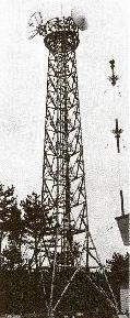
Note 1 - This station had a 200 meter mast. Typical mast height in the Japanese chains was 120 meters.
Note 2 - The announcement that Japan was going to add a third Decca chain came in June 1973. Multipulse (MP) equipment was installed at the onset at the Tohoku. Experimental transmissions began in 1974.
Note 3 - This Purple station was added later.
Note 4 - The four stations of the Kyushu chain transmitted on an experimental basis from December 1968 until April 1969 when they switched to 24 hour operation. The mast heights of the stations were 150 m.
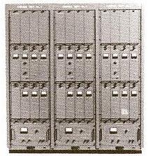
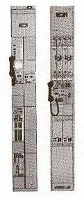
TYPICAL STATION CONFIGURATION
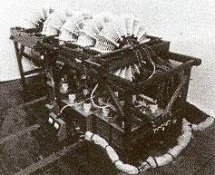
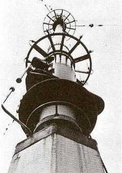
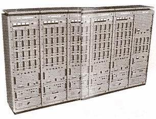
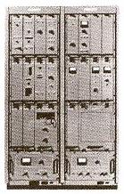
Depicted below are the elements of the Decca site of the Mikuni master station in the Hokuriku Chain.
It is believed the Japanese based their equipment design on the Decca 1880 series of equipment as there are many similarities in the design. In particular, there was additional metering added to each cabinet.
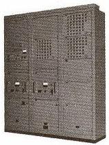
Helix Coil System- Connects between the transmitter and antenna. Transmitting Antenna - Connects to Helix Coil System. The spark gap can be seen at the left of the photo Decca Transmitter Set - Interconnects with Phase Control and Switching and Control Panel.
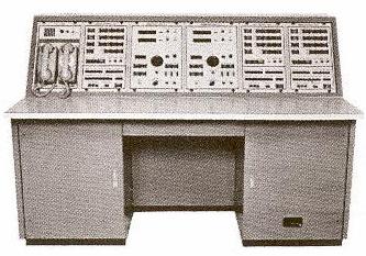
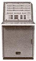
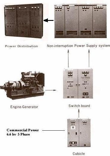
Switching and Control - Connects to Helix Coil System, Decca Transmitter Set, Phase Control Cabinet and Remote Control Equipment. Phase Control Cabinet - Interconnects with the Decca Transmitter Set and the Switching and Control Panel. Remote Control Equipment - Connects with 2 GHz Transmitting/Receiving Equipment, Switching and Control Panel, Control Desk, and Monitor and Control Desk. Control Desk - Connects to Remote Control Equipment, 2 GHz Transmitting/Receiving Equipment, and Monitor/Control Console. Monitor and Control Console - Connects to Control Desk, Remote Control Equipment, and 2 GHz Transmitting/Receiving Equipment. 2 GHz Transmitting Receiving Equipment - Connects to Remote Control Equipment, Control Desk and Monitor. Control Link Antenna - Only connects to the 2GHz Transmitting/Receiving Equipment. Station Power System All images provided by the Sena Company Ltd., Tokyo, Japan THE OPENING OF A CHAIN IN JAPAN
The opening of a chain in Japan was always a colourful occasion. The ceremonies commenced with the Blessing of the Project by Shinto Priests with the assistance of representatives of the Government, the Japanese and US companies involved with the installation plus Decca itself. After the Blessing and the traditional drinking of sake from silver cups, the station near Fukuoka was inspected. The immaculate interior of the buildings caught everyone's attention. Japanese tea was served and the party then went to the city of Fukuoka where speeches were read before several hundred guests.
The speeches were followed by a banquet given in the Nishitetsu Grand Hotel (Fukuoka) where a special display of equipment had been arranged for guests who were not familiar with Decca Navigator to see how the system was used. Many charts, diagrams, photographs, etc. were on display together with a receiver (the Fujitsu MS1A which was widely used in Japanese waters) operating from the newly opened chain. During the meal, traditional songs and dances were performed.
In the evening, the guests assembled for a Japanese style banquet given in a fine old building constructed of wood and paper. Seated on the floor, surprising quantities of raw fish, bean curd, seaweed, rice, beer and whisky were consumed in an atmosphere of old Japan. Splendid entertaining was given by Geisha girls whose singing and dancing were interrupted only for a speech of thanks by the Deputy Director-General of the Maritime Safety Agency, Mr Hayashi, and the presentation of silver commemorative medals on behalf of the Decca Company of London.
Credits and References:1) Decca Navigator News , March 1970
July 29/12
Aug 3/12