|
| Mk IV - Front View (Photo from the collection of Walter Blanchard) |
 |
| Mk IV - Rear View (Photo from the collection of Walter Blanchard) |
Decca Airborne Developments (From "The Aeroplane" magazine, June 3/1949,.
Decca Air Data Sheets ( March 1949)Marks 6, 7, 8, 9, and 10 were all airborne-only receivers. Mk 4 was available in both airborne and marine versions
|
| Mk IV - Front View (Photo from the collection of Walter Blanchard) |
|
| Mk IV - Rear View (Photo from the collection of Walter Blanchard) |
Type: Mark IV (MkIVA airborne version shown above)
Input Power Requirements: Airborne - 80 VAC at 1000 cps at 80 watts.
12 VDC at 90 watts.
24 VDC at 90 watts.
Marine - 110 VDC at 90 watts
Display: 1 set of decometers
Number of Channels: 4 (Master, Red, Green and Purple)
Dimensions: 15.5 x 15 x 7.5 inches
Weight: 25
Quantity Produced: ??
Purpose: Airborne navigation
Comments: Receiver in production as of 1946. Sub-designated QM 's 6,7,8,11,13 depending on chain and frequencies. The very first Mk 4 receiver was fitted to M.V. ROGATE (Stephenson Clarke Shipping) on Feb 26, 1947Variant: MkIVA was used for airborne navigation.
Mk 6 RECEIVER
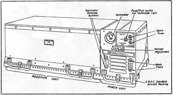
1949: Decca Mk 6 Aircraft Receiver. (Photo from the collection of Walter Blanchard) This diagram shows the external controls of the MK 6 receiver. (Image from the collection of Walter Blanchard) SPECIFICATIONS
Receiver Dimensions: 21" W x 8.5" H x 11" D.
Receiver weight: 24.5 lbs.
Capability: Can receive up to 5 chains. Remotely controlled from cockpit.Power Unit Dimensions: 6"W x 8.5"H x 11"D
Power Unit weight: 19 lbs.
Power Input 24 VDC@ 12.5 amps
Comment: Airborne receiver electrically similar to Mk. 5. MK VI data sheet
 |
| Pilot's remote control for the Mark 6 receiver. (Decca Navigator Company image) |
 |
| 1949: Mark 6 decometer panel. (Courtesy "The Aeroplane", June 1949) |
FLIGHT PLOTTERTo simplify the problem of navigating in all types of aircraft, Decca came up with a solution in the form of a presentation suitable for pilot navigation.
Simple route graphs prepared by the Decca Navigator Company for all European air routes were inserted in the Flight Plotter and the pilot only needed to turn the knobs of the Flight Plotter to bring the perspex cursor to correspond to the Decometer readings at any point on his flight, to obtain, without further effort, not only a position fix, but also range and bearing from destination. The pilot was entirely free to make any deviation from route when circumstances necessitated and was able to use this simple and efficient method of navigation throughout his flight.
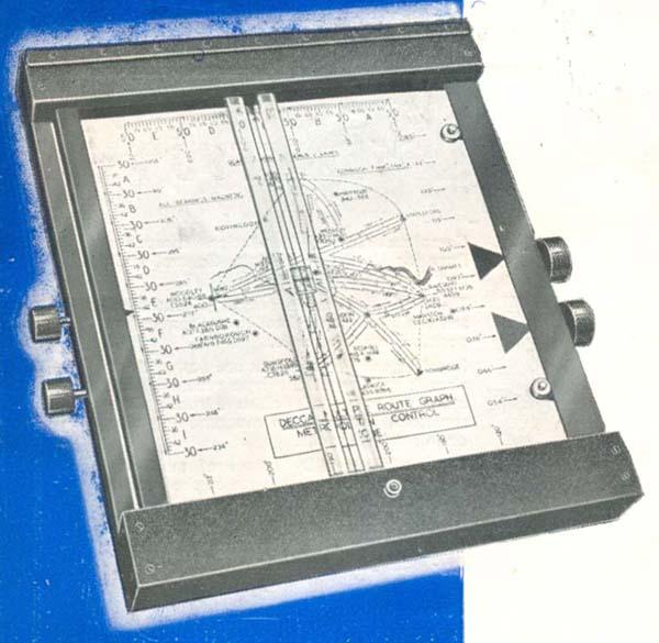 |
1949: Decca Flight Plotter. Click to enlarge. It bears no model or part identification because it was the very first one that Decca produced. The complete Flight Plotter illustrated here contains the Route Graph for the Metropolitan Control Zone, which enabled the pilot to continuously and accurately plot his approaches along the corridors to the principal Metropolitan airfields in Europe. Weight of the Flight Plotter is 4.5 pounds and its dimensions are 12"W x 14" H x 2"D. (Decca Navigator Company image) |
This device, in conjunction with the Decca Navigator Mark VI receiver and the existing Decca chains of the day provided a realistic and practical aid to navigation in Europe.
| SAMPLE ROUTE GRAPHS FOR THE FLIGHT PLOTTER | |
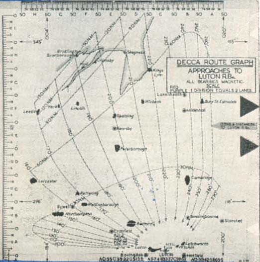 |
Click to enlarge. This is the Route Graph for the area north of London enabled range and bearing from Luton Control Point to be obtained at any time during the flight. This. Route Graph was used for general flying in this area and for all routes running into the London Control Zone from the North East area. (Graphic courtesy Decca Navigator Company) |
 |
Click to enlarge. The Route Graph shown here is for a typical European air route such as Brussels to London. (Graphic courtesy Decca Navigator Company) |
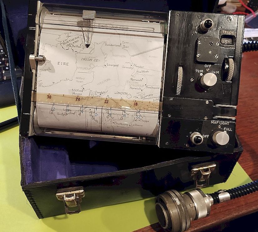
FLIGHT LOGThe Decca Flight Log was a logical extension of the Flight Plotter and was made possible by the use of the new map projection technique used in the Flight Potter. The map of the route to be flown was carried on a cylinder, measuring 16 inches in length and 7.5 inches in diameter. As the cylinder was rotated about its axis by the drive unit, it was traversed by a Perspex scale. A marker carried by this scale made, on the map, a continuous recording of the track of the aircraft over the ground.
As was the case with the Plotter, the map could be varied to suit particular requirements. Complete flights of up to 300 miles could be covered on one map, with separate diagrams to cover the approach pattern, traffic holding procedure, etc.
Decca co-ordinates would not normally be marked in on the map but would be printed in the appropriate colours on the reverse side. If it was desired to check the Log for accuracy, the inside of the drum could be illuminated, to make the co-ordinates visible. Readings could then be taken from the receiver and plotted in the usual way on the map. A time plotter was also provided for optional use. When switched on, it caused the pencil marker to deviate at given intervals and thus provided a record not only of the track flown by the aircraft, but of the time taken over various sections throughout the flight.
Apart from the obvious value of the Log for navigational use, it had an important application as a flight recorder. The installation of a Log in the rear of an aircraft used for navigational training, for instance, would enable a complete picture of the pupil's flight to be obtained and a post morteum could be held if necessary. Similarly, aircraft operators would find the installation of a Log useful as a means of checking the movements of their aircraft.
In 1949, the Flight Log only existed in prototype form and flight trials had not yet commenced. It had, however, been extensively tested in road trials, and some impressive results were obtained. In one test, a vehicle equipped with the Flight Log had a run down the Kingston By-pass (in the UK). The engineers watched the Log draw a line accurately down the centre of the road marked on the map. They did however, notice that telegraph and trolley bus wires sometimes caused serious deviations. At short ranges, this would make road use of the instrument impracticable. It was anticipated that Flight Log would be available by 1950.
 |
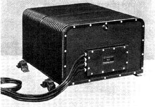
| Essential components of the Flight Log were a torque amplifier, a drive unit, a display unit, and the Mark 6 Decca Navigator Receiver which fed the drive unit. In 1949, only prototypes of the Flight Log were available. (Decca Navigator Company photo) |
Mk6A DISPLAY HEADA Decca Omnitrac installation provides for the pilot, a pictorial display on which the present position and track of an aircraft is continuously plotted. The system uses Dectra, Loran C, and Doppler for long range overwater flights, and Decca, VOR/DME and Doppler for short range flights. Automatic guidance through the autopilot along any selected flight path is included.
The pictorial display provides a marked advance in reducing the cockpit workload by clearly showing the aircraft position on a chart, thus eliminating mental effort in estimating position. Safety is improved by clearly plotting the relationship of the aircraft to known geographical hazards. Accuracies in the order of a few miles have been observed on transatlantic flights. Accuracies are measured in yards under short range flight conditions.
The Mk. 6A Display Head was used with the OMNITRAC system. It accepts VOR/DME, Doppler, Inertial as well as Hyperbolic inputs all piocessed and fed to the display head by the OMNITRAC computer. The system provides bearing and distance and ETA read out to any selected point, autopilot coupling, L/R indication and it also solves the problem of circling approaches. (Image via E-bay)
Mk 7 RECEIVERThis is an airborne receiver using locked oscillator with a phase comparison directly at slave frequencies.
The Mark 7 receiver was developed to meet the increased speed requirements of jet aircraft. In the Mark 7 design, the signals received from the ground stations are compared without multiplication against a local oscillator locked to the Master station. By this means, the Decca lanes are effectively increased by 3, 2 and 6 times the width normally used for Red Green and Purple.
In the standard Decca receiver, ( ie the Mark 8) an aircraft flying along the base line between Master and Slave could possibly loose lanes if its speed was above 240 knots. With the Mark 7 equipment, full Decca facilities are provided to aircraft travelling at speeds of up to 1,500 mph without any risk of lane loss.
 |
| Mark 7 receiver - principle components. (Courtesy Decca Navigator Company) |
 |
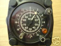
| Mark 7 receiver decometers. (Courtesy Decca Navigator Company) |
Mk 8 RECEIVERAirborne receiver same as Mk. 6 but fitted in standard SBAC racking.
This receiver was used by the RAF. In 1955, eight Valiants and ten Shackletons were fitted with Mk 8 receivers and flight logs for Operation Grapple, the nuclear bomb tests at Christmas Island. It was also by (former) British European Airways on their Argosy freighter aircraft. The Ledex switch assemblies used in the Mk8s were often the root cause of many problems although the tubes seemed to have a very long life span and were not changed that often.
Variant: Mk. 8A - Airborne receiver based on Mk. 8 but fitted in smaller half-ATR ARINC racking.
Mk 8 receiver components. Source DECTRA marketing brochure. (Photo courtesy Decca Navigator Company)
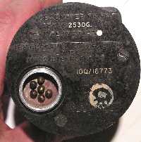
Closeup of the RED Mk VIII aeronautical decometer. Type 274-Z. P/N 10Q316774. (E-bay photo) Rear view of GREEN Mk VIII aeronautical decometer. Type 274Z. P/N10Q16773 . (Photo courtesy Denis Chouinard)
 |
| Manual cover for Mk 8 equipment. The rest of the manual is not available. (Image via E-bay) |
Mk 9 RECEIVERAirborne receiver without Land Identification feature.
Mk 9 receiver components. Source DECTRA marketing brochure. (Photo courtesy Decca Navigator Company) Mk 10 RECEIVER
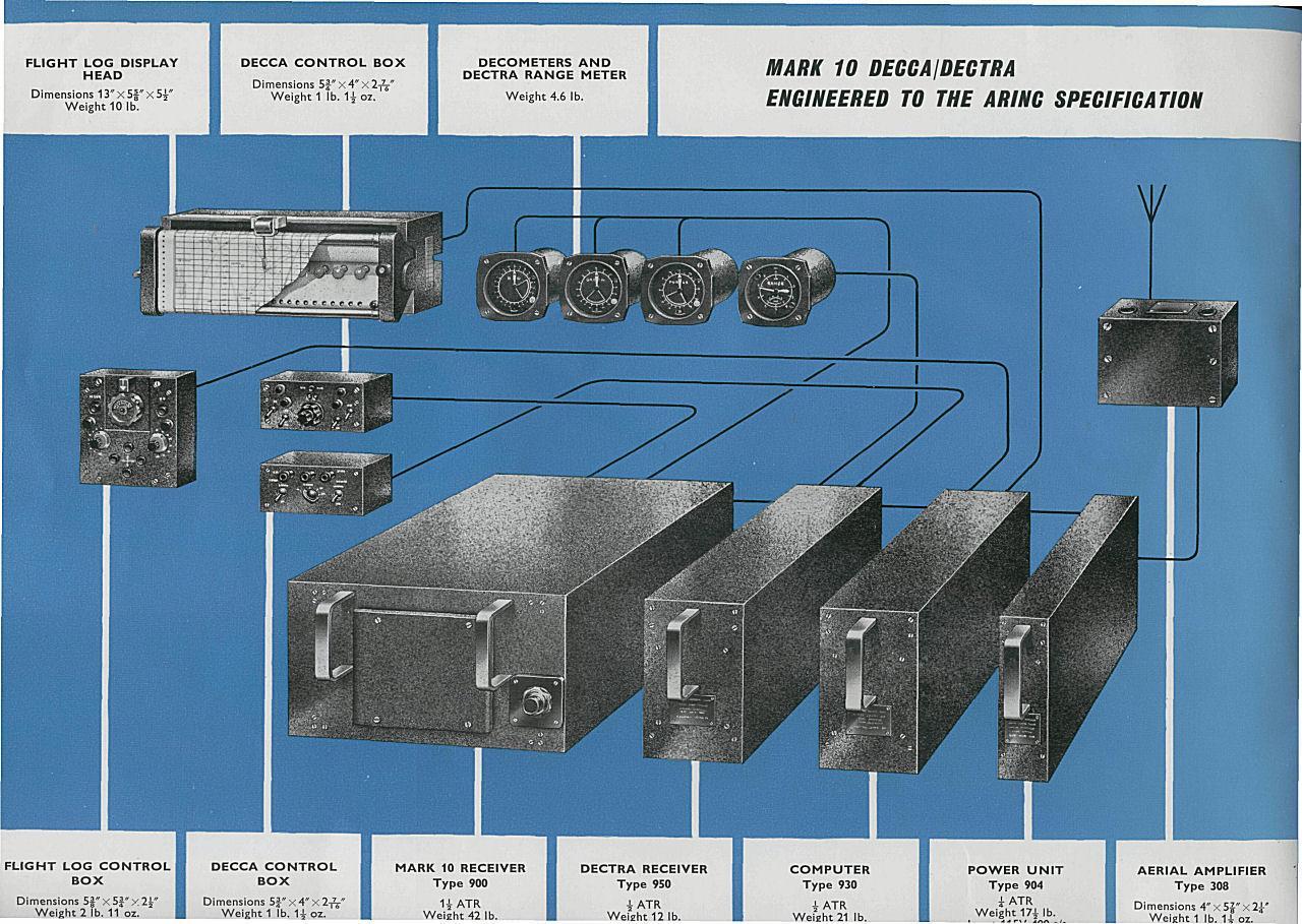
Major new design of the airborne receiver for use in the DECTRA system . It employed locked oscillators on all channels; automatic Lane Identification using the Multipulse method; had the zone identification feature; phase comparison at 1F (14 kHz).
Mk 10 receiver components. Click to enlarge. Source DECTRA marketing brochure. Mk 10 receiver dimensions/weight: 24 in W x 15.5 in D x 9.25" H / 50 lbs. (Photo courtesy Decca Navigator Company)
 |
| Mk 10 receiver with cover off and two modules extended for service. (Decca Navigator photo) |
Mk 11 RECEIVERFirst solid-state receiver. Used with the Omnitrac/Harco system. Employed electromechanical tracking filters and digital outputs.
Mk 14 RECEIVER
This was an airborne receiver prototype using locked oscillators s on all channels and outputs at 1F for external phase comparison. No Lane Identification or Zone Identification.. It was a simplified version of Mk 15 working only in the integration mode.
Mk 15 RECEIVER - DANAC
This was a development of the Mk. 14 receiver for use in DANAC incorporating full Land Identification and Zone Identification. Used with computer types 1910 or 9810.
The Mk15s were used on British European Airways Trident aircraft, and were also a standard fit in many UK registered Jet Ranger helicopters. On the Mk15s, various transistors often failed along with crystals. One of the most common "squawks was that the radio would not sync up, primarily either on Red, Green or Purple. This was due to either crystal aging or mechanical damage (drop shock) and hence no sync.
 |
| Mark 15 receiver system. (Photo from the collection of Walter Blanchard) |
DANAC stands for Decca Area Navigation Airborne Computer. In this system, the position-fix information delivered by a Decca Navigator receiver is continuously presented, via the computer, on a Flight Log pictorial display. This product was introduced in 1969.The system is largely automatic, but permits the user to monitor all stages of operation. A basic principle is that the computer, during initial setup and under certain other conditions, requests the user to confirm that he accepts the displayed position of the aircraft. If the position is not acceptable he can adjust the display using the prescribed procedures.
A) In addition to the Danac units, the Mark 15 system has an antenna amplifier Type 1995
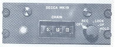
B) The additional units of the Mark 19 system are:-Antenna amplifier Type 1995
Mark 19 receiver Type 1904
Receiver controller Type 8954
Decometers (red, green, purple) Type 274
Lane identification meter Type 275
Zone identification meter Type 1956Although Danac can work in a restricted mode with Decca chains of the early type (known as V or sometimes Mark V chains), it is intended for use with MP chains. This term stands for the multipulse (also known as Mark 10) signals which the chain radiates every 20 seconds. The MP signals perform an automatic function in the receiver known as "notching" or automatic lane setting, with the object of resolving ambiguities that could otherwise permit the displayed position to be in error by some fraction of a zone, and also provide zone identification. More on MP in the Decca Transmitter section.
 |
| DANAC airborme computer model 9851F (Via E-bay) |
Mk 16 RECEIVERIt was the same as Mk.15 but with phase comparison circuits built-in; it had fractional zone outputs for the OMNITRAC system and was specifically designed for use with the Omnitrac computer
Mk 16 saw service during the early days of testing the supersonic Concorde aircraft and more specifically, during the period of Concordes Inertial Navigation System certification. It was built in a ¾ long ATR case and was essentially a Mk 15 with the navigation computer bolted on the back. Specially selected components were incorporated in this radio and it did track even when the aircraft was flying supersonic.
Mk 17 RECEIVER
This was a Mk. 16 receiver modified for use with the DECTRA System and for use with the Omnitrac computer.
Mk 18 RECEIVER
This was an experimental, batttery operated "mini DECCA" system for the British Army, not an airborne set..
Mk 19 RECEIVER
A multi-purpose unit for military use which incorporated both Mk. 8 and Mk. 15 facilities. It could be retro-fitted into Mk. 8 racking. Mk 19 was used by RAF.
There was also a special military receiver known in Decca as the "Type 990" and known by the RAF as "Mk 1 (Air)" . It had special anti-jam and other features. Quite a lot of them were built and fitted into Canberra aircraft in the late 1960's.
Receivers such as the QM5, QM9 and QM10 could only receive the standard 'V' type transmissions. Mark 12 receivers were designed to receive both Mark V and the newer Multipulse (MP) transmissions.
Due to the need to have stable, accurate monitoring site performance, a lot of research went into antenna design. An active antenna was designed for station monitoring that had a graphite coated radome designed to reduce
interference from charged water particles. The Mk 21 used a short, stubby, cylindrical antenna, approximately 24 inches overall and 3.5 inches diameter. This included a head amp and was connected via a single cord to the receiver.Monitoring vehicles were fitted with Mk 12 and Mk 21 receivers for purposes of monitoring chains. These used a mixture of antennas including a lab-made custom design comprising of a 2 foot of 6 inch pipe with a metal sphere cap (not recommended for low headroom parking).
This is the receiver control unit ( Type 8954) for the Mk 19 airborne Decca receiver (Photo courtesy Decca Navigator Company)
There was a later version (Mk30 perhaps) receiver that used a ring of LED segments to form the decometers but it not clear if these ever went into production. The analog Decometer-type display always seemed to be more reassuring than static lights.Select this link to view the various modules which comprise the Mk 19 receiver.
For more info on the Mark 19 receiver, select this link.
This was the airborne version of the Decca receiver called Dectrac Mk 19/15A3 s/n 175 built in 1980. (Courtesy of web page: http://perso.libertysurf.fr/webmeynier/aero/
80084.htm)
The Model 961 flight indicator was part of the Mark 19 system and was used by the RAF mainly in helicopters and the Hawker Siddeley Andover Transport aircraft. The unit depicted (s/n 209) was manufactured in May 1974. Click on photo to enlarge. (Photos by Santiago Insua)
Model 9063 Mk 3 Rolling Map Display, Click on image to enlarge. At this time it is not known as to which system the display was part of. If you can provide an answer, contact: jerry.proc@sympatico.ca (Photo by David Edwards) MODERN EQUIPMENT
By the end of the Decca system, the receivers were designed with built in processors. The display would read latitude and longitude directly thus dropping the need to procure and use lattice charts.
Two examples of direct reading Decca receivers are the Model SAH-1D (left) and the Navigator DR-702. The model SAH was sold to the Japanese market hence the reason for the Japanese characters on the keypad. (Photo courtesy of the Sena Co, Ltd, Tokyo, Japan).
Additional references or credits:1) Walter Blanchard <wb(at)g3jkv.co.uk >
2) Danac Operating Instructions Manual, June 1979. Decca Navigator, New Malden, Surrey
3) Extracts from Decca's Genealogy provided courtesy Walter Blanchard, Royal Navigation Institute.
4) Stuart A Wolf <stuart.wolf(at)nats.co.uk>
5) James Morrison Decca photos. http://www.flickr.com/photos/jamesm/107572653/in/set-72057594120797676/
6) DECTRA marketing brochure published by the Decca Navigator Company.
7) Denis Chouinard <denischouinard(at)enter-net.com>
8) Santiago Insua <hwasp(at)hotmail.com>
9) Matthew Parker <parkermat(at)hotmail.com>
10) David Jones <dsjjones(at)bellsouth.net>
11) Decca NAvigator Airborne Equipment brochure.
12) Decca Mk 6A https://www.sae.org/publications/technical-papers/content/680298/Oct 24/24