MARINE RECEIVERS & INDICATORS
(Survey and special-purpose receivers, e.g. Type 990 (RAF Mk 1 Air)
not included in this document).
QM Receiver
|
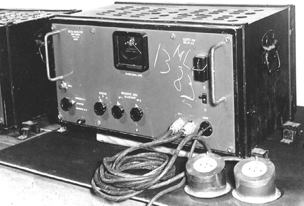
| Here's where it all started. This was one of the original Decca
receivers which saw action on D-Day. Designated Outfit 'QM' , it
was fitted aboard Harbour Defence Motor Launch 1383, which was one
of the vessels actually used on D-Day for survey work on the beaches. Someone
has inscribed the vessel's pendant on the front panel. The serial number
of the unit (s/n 112) is actually unit number 12 in the first build series
(Photo
from the collection of Walter Blanchard) |
Type: QM
Input Power Requirements: 220 AC at 100 watts
Display: 1 pair of decometers
Number of Channels: 3 (Master, Red, Green)
Dimensions: --
Weight: --
Quantity Produced: 27
Purpose: Prototype receiver for marine navigation
Comments: Developed as a secret wartime navigational aid for the British
Admiralty.
 |
| The original decometers were of the gas meter type, and as
such, the first Decca display ever made. Printed on the dial is the name
DR&T, London. which is an abbreviation for Decca Radio & Television.
The gas meter name was used since they were originally made from domestic
gas meters which were designed to count in multiples of ten. (Photo
by David Jones) |
 |
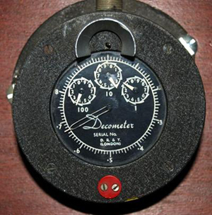
| A "gas meter" style decometer in its natural
brass finish. The Green circle at the 6 o'clock position means it was used
as a readout for a Green slave transmitter. (Photo by Mark Ramsay) |
 |
| Exploded view of a newer style of decometer.
(Image
from Decca Navigator News, May 1951). |
The newer Decometer, an exploded view of which is shown above,
consists essentially of a magnetized soft-iron disc C turning inside a
yoke A upon which two pairs of stator coils B are mounted at right-angles.
The Receiver, picking up signals from the Transmitting Chain, feeds its
output to the two pairs of coils in the form of two separate DC currents,
the relative strength and polarity of the currents varying in accordance
with the relative distance of the Receiver from the Master and Slave stations.
When the receiver is exactly on a Decca lattice line, that is, on a
line of zero difference, current is applied to only one coil, the magnetic
field of which lies in such a direction as to pull the disc round to its
'zero' position. In this position, the Fraction Pointer E, which is mounted
directly on the disc-spindle D, points to Zero on the dial. As the ship
or aircraft moves off the lattice line, current starts to flow in the other
coils and the disc and pointer turn to new positions following the changes
in direction of the magnetic field set up by the coils. As the receiver
travels across the Lane, the disc completes one revolution and the pointer,
at the next lattice line, arrives again at Zero on the dial. The crossing
of sucessive Lanes is recorded by the Lane-Number pointer I. A further
stage of gearing drives the Zone Letter Dial J.
Since the Fractional Pointer sweeps a scale marked in hundredths of
a lane, the highest degree of accuracy in the meter movement is demanded.
Infinite care must be taken in making and mounting coils and yoke, and
the whole
assembly is of watch-like precision, including jewelled bearings. On
each Decometer is a 'Reset' knob K, which works like the hand-setting knob
on a watch, allowing the pointers to be set up manually. Pressing the knob
brings the wheel L into mesh with the gear train. The 'Zero' knob,
M, enables the whole assembly F to be rotated by hand, so that if signals
known to be of zero-phase-difference are fed into the Receiver, the Fractional
Pointer can be brought exactly into line with the zero mark on the dial.
The signals of each 'colour' required for this setting up are artificially
generated in the Receiver and are switched in by pressing the 'Ref'
button, N, mounted on one
of the Decoometers.
Another Decometer in the set, carries a 'Test' button in place of 'Ref'
which, when pressed, causes a deliberate phase-shift to be applied to the
Master Channel in the Receiver. So long as all the signals from the Chain
are
being correctly received, each Fractional Pointer will deflect in response
to this phaseeshift, and so give a check on the working of the whole
installation.
QM1 Receiver

|
| QM1 receiver. In the Royal Navy, it was
designated as the QM1. (Photo from the collection of Walter Blanchard) |
Type: QM1
Input Power Requirements: 220 VAC at 90 watts; mains only operation.
Receiver: B37
Display: One pair of decometers, red/green only.
Dimensions: 21.25 x 16.25 x 12.25 inches
Weight: 80 pounds
Quantity Produced: 40
Purpose: Marine Navigation
Comments: Further development of QM receiver. Used extensively by the
Royal Navy
for mine clearance in the Scheldt Estuary prior to the re-opening of the
Port
of Antwerp in Belgium at the end of WWII.
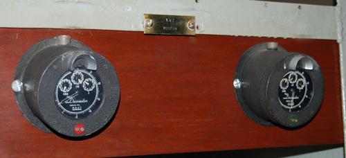 |
| The gas meter decometers were fitted with mounting flanges and when
mounted, had a slight downward cant. A red or green marker on the front
denoted the channel. The cable to the receiver plugged into the top of
the unit. This display can be found aboard HMS Belfast in London. (Photo
by David Jones) |
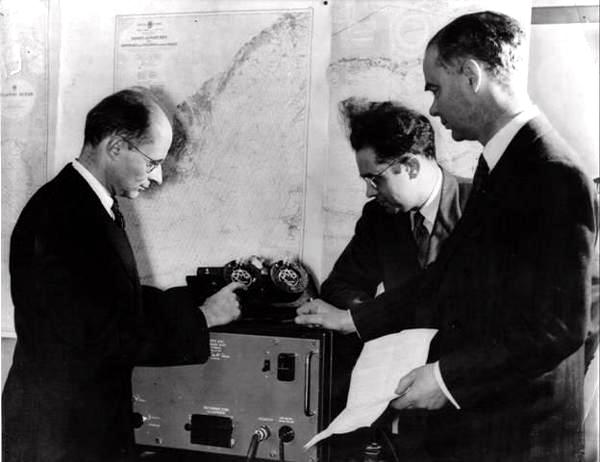 |
| Modified QM1. The two knobs on the front panel of the QM1 receiver
controlled the zero adjustment for the Decometers - one for each pattern.
They were somewhat sensitive, so later production runs had a small, hinged,
black cover plate installed to cover them up so they couldn't be accidentally
knocked out of adjustment. This gives the initial impression that they
were two different receivers but they were not. Harvey Schwarz is at the
left, Bill O'Brien in the middle and on the right is Edward Lewis, (later
"Sir") Chairman of the Decca Group.(Photo from the collection of Walter
Blanchard) |
QM2 Receiver
 |
| QM2 receiver. (Photo from the collection of
Walter Blanchard) |
Type: QM2
Input Power Requirements: 12 VDC at 8 watts; battery operated.
Display: 1 pair of decometers. Similar in operation to QM1.
Number of Channels: 3 (Master, Red, Green)
Dimensions: 18 x 16.5 x 7.5 inches
Weight: 32 pounds
Quantity Produced: 30
Purpose: Portable survey receiver for general use.
Comments: Portable battery powered receiver developed primarily for
use on small ships.
Not equipped for operation on 220 VDC mains. Suitable for general use on
land or
in the air. Used by the Royal Navy in the Scheldt sweeping operations.
 |
| In this historic photo, Bill O'Brien (L) and Harvey Schwarz (R)
study a QM2 receiver. Note the QM1 receiver sitting on the bench adjacent
to the drafting board. (Photo from the collection of Walter Blanchard) |
QM3 Receiver
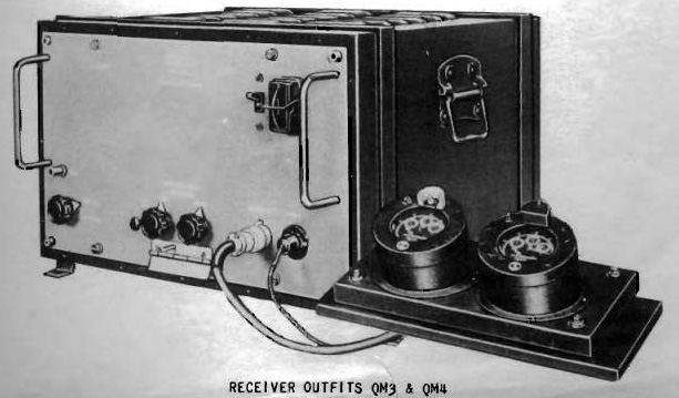 |
| QM3 and QM4 receiver outfits. (Photo courtesy Museum
of Radar and Communications) |
Type: QM3
Input Power Requirements: 220/240 VAC 50/60 Hz at 200 watts
Display: 2 pairs of decometers: Indicator Meter Design 3 65701)
and Design 4 (65702)
Receiver: B49 (66671)
Channels: Master 85 KHz; Red 113.3 KHz; Green 127.5 KHz
Dimensions: 21.25 x 16.25 x 12.25 inches
Weight: 80
Quantity Produced: 40
Purpose: Marine navigation
Comments: Modification program to QM1 receiver . Receiver output stages
modified
and two pairs of decometers fitted to permit remote presentation of meter
readings. Slightly smaller than QM1. Outfits QM3 and QM4 could only be
used with the English chain whose Master station was located at Puckeridge,
about 18 miles north of London. .
QM4 Receiver
Same as QM3 outfit except that it used Master 85 KHz; Red Slave
(113.3) and Purple Slave (70.833 KHz) stations to obtain a position. Comp[rised
of B53 receiver, Indicator Meter Design 3 65701) and Design 4 (65702)
EARLY DECOMETER BOWL
 |
| This three meter decometer bowl is awaiting identification but believed
to be from around 1948 since it lacks the Lane Identification feature.
Decca's Decometers were made by a small British instrument company called
Reid and Sigrist. Because it was such a vital item Decca eventually bought
the company and it became part of the Decca Group. (Photo by David Jones) |
Mark III Receiver
 |
| Mark III Receiver. (Photo from the collection of Walter
Blanchard) |
Type: Mark III
Input Power Requirements: 12/24 at 65 watts for airborne version; 110
VDC at 70
watts for marine version
Display: 1 pair decometers
Number of Channels: 3 (Master, Red, Green Purple)
Dimensions: 18 x 16.5 x 8 inches
Weight: 27.5 pounds
Quantity Produced: Seven 12 volt versions; seven 24 volt versions;
46 marine versions.
Purpose: Either an airborne or marine receiver depending on power source.
Comments: As an airborne set, it was produced for trials only. As a
marine set, they were produced in limited quantity primarily for the Ministry
of Transportation trials.
Mark IV Receiver
 |
| Mk IV - Front View (Photo from the collection
of Walter Blanchard) |
 |
| Mk IV - Rear View (Photo from the collection
of Walter Blanchard) |
Type: Mark IV (MkIVA airborne version shown above).
Available in marine version.
Input Power Requirements: Airborne - 80 VAC at 1000 cps at 80 watts.
12 VDC at 90 watts.
24 VDC at 90 watts.
Marine - 110 VDC at 90 watts
Display: 1 set of decometers
Number of Channels: 4 (Master, Red, Green and Purple)
Dimensions: 15.5 x 15 x 8 inches
Weight: 31.5
Quantity Produced: --
Purpose: Marine navigation
Variant: MkIVA was used for airborne navigation.
Comments: Receiver in production as of 1947. Sub-designated QM 's 6,7,8,11,13
depending on chain and frequencies. The very first Mk 4 receiver was fitted
to M.V. ROGATE (Stephenson Clarke Shipping) on Feb 26, 1947. Withdrawn
from production in 1966.
The receiver was designed to only receive the English chain but was
later adapted for the Danish and other chains. It did not incorporate
the facility of Lane Identification which wasn't developed until 1948.
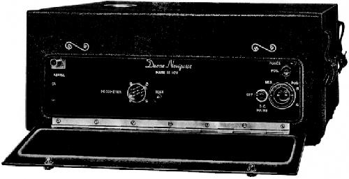
 |
This is a two range decometer, used on two range
Lambda Survey Chains for offshore surveys and was manufactured in the 1960's.
The model number indicated is 9039AA Click image to enlarge.
(Photo
courtesy V.K.Lehtoranta, OH2LX) |
Mk V Receiver and Display
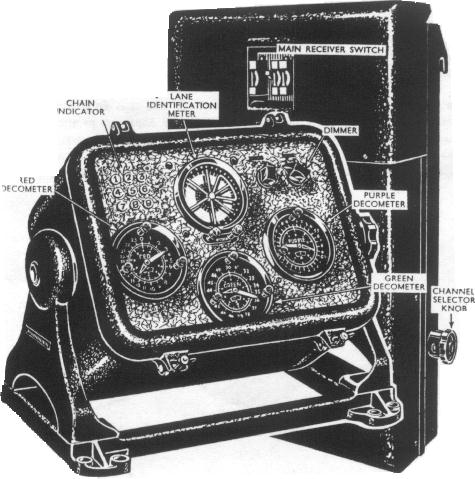 |
| This is the Decca Mk V (QMS 10). On the left is the decometer
bowl. At the right is the receiver. Reading clockwise from the upper left
corner of the decometer bowl are: Chain Indicator, Lane Identification
Meter, Dimmer control, Purple Decometer, Green Decometer and the Red Decometer.
On the receiver, it is Main Receiver Switch at top center and Channel
Selector Knob at the right side. (From BR-45 Admiralty Manual of Navigation). |
Type: Mk V
Input Power Requirements: Airborne - 24 VDC at 90 watts.
Marine - 110 VDC at 90 watts
Display: 1 set of decometers
Number of Channels: 4 (Master, Red, Green and Purple)
Dimensions: 12 x 15.5 x 8 inches (airborne version)
15.5 x 16.5 x 7.75 inches (marine version)
Weight: 20 pounds (airborne)
62 pounds (marine)
Quantity Produced: --
Purpose: Airborne and marine navigation
Comments: Under development in 1946. The picture above is copied from
the Admiralty Manual of Navigation , 1955. The was Decca's first marine
receiver capable of lane identification. Also applicable to QM's 5,9 and
10.
It should be noted that the Royal Navy used a different designation
for its Decca receivers. All their receivers were purchased, not
rented and although they were the same as the commercial models,
they used the number code QM.
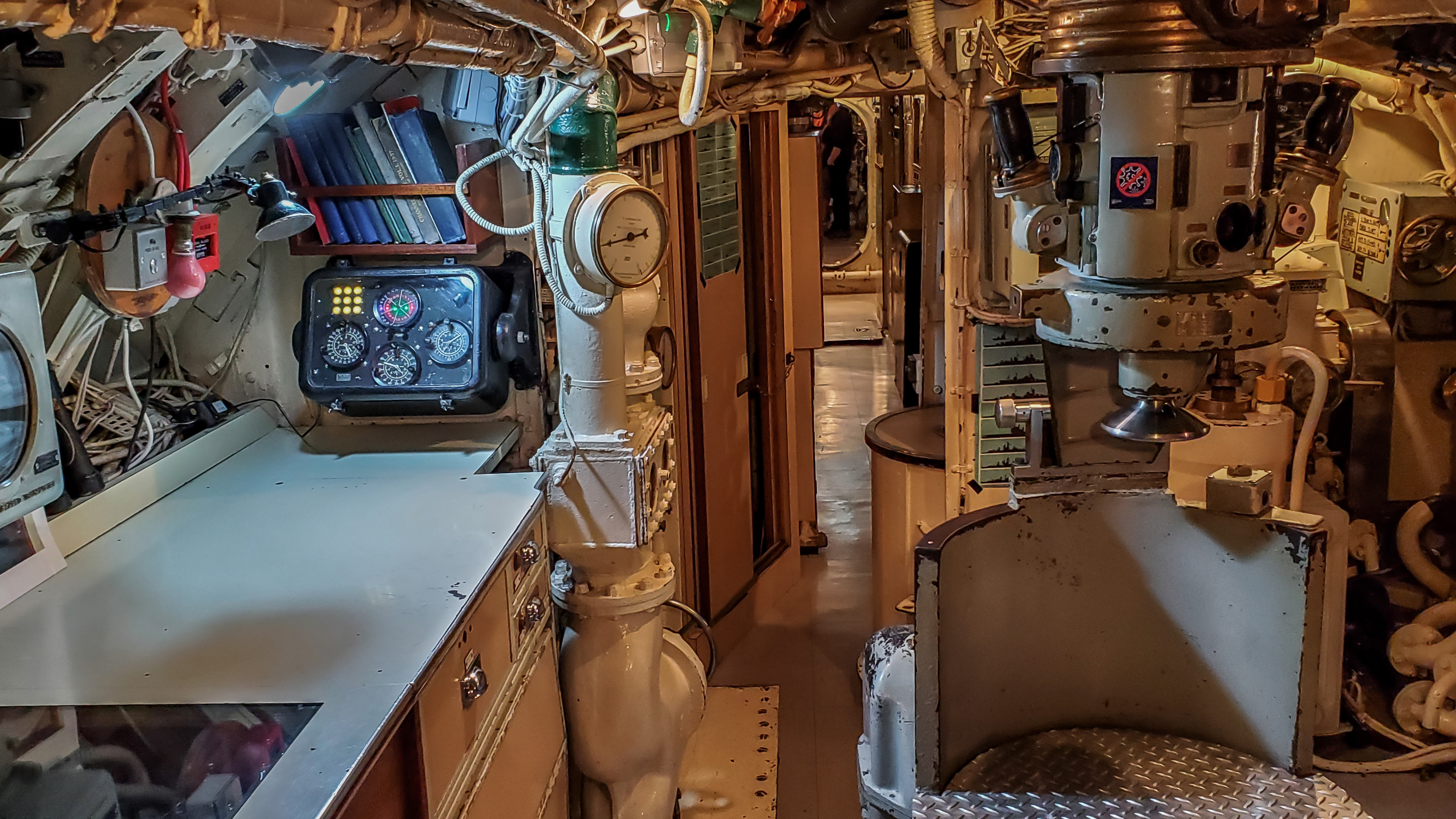 |
| Here is an example of a Mk V decometer fitted
aboard HMS Alliance, a British submarine commissioned in 1947 and now a
museum. Click on image to enlarge. (Photo by David Jones) |
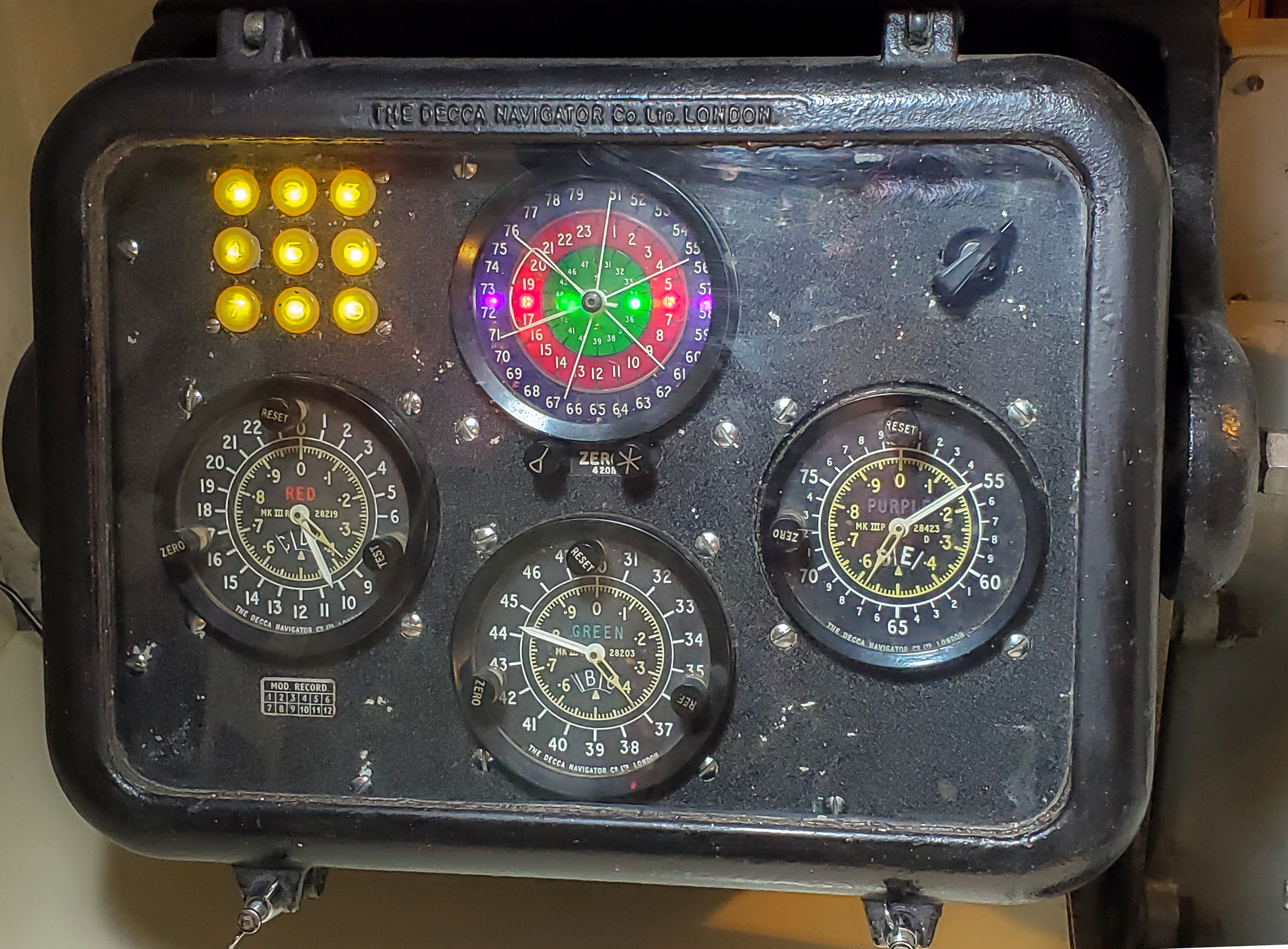 |
| The Mk V decometer aboard HMS Alliance has been
modified so that all the chain indicators and lanes lamps illuminate.
The Mk V receiver was likely used for inshore navigation whilst traveling
on the surface. Click on image to enlarge. (Photo by David Jones) |
 |
| Mark V receiver with chassis cover removed. (Photo courtesy Patrimoine
Radiomaritime web site http://pierre.painset.free.fr) |
MARK XII EQUIPMENT
Decca introduced the Mark XII (valved) marine receiver on 1962 Nov 27,
1962. It supported both Multipulse and Mk. 5 Lane Identification in order
to work with all chains. Used a locked oscillator in the master channel.
The receiving antenna for the Mk 12 style of receiver was normally a
3 part fiberglass tube with a single wire inside. Overall length was about
15 to 18 feet and it came with a wall-plate for fixing to bulkhead or building
wall. Tube diameter was about 1.5 inches and it tapered slightly. The Mk
12 receiver was a wall mounted unit with screw connections via the base.
Decometer and power unit were separate to the receiver. Inside the receiver
unit, the electronics were on 4(?) full length swing down modules. These
receivers were also used as fixed monitors for the chains. These
receivers were also used as fixed monitors for the chains
 |
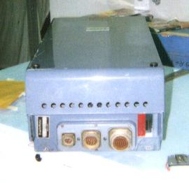 |
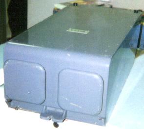
| An example of a Decca Mk12 receiver. At the left is the
top view; the bottom view is at the right. The chain monitoring receiver
was a modified Mark12 unit. (Photos courtesy Maritime Museum
of the Atlantic). |
 |
| An internal view of the Mk 12 receiver showing one of the chassis units
swung down for servicing. (Courtesy Decca Navigator News April, 1972) |
 |
| Here is an example of a Decca Mk12 decometer bowl which was donated
to HMCS HAIDA National Historic site. One major change from the Mk
V to the Mk XII system was the relocation of the chain selector switch
from the receiver to the decometer bowl. (Photo by Jerry Proc) |
The decometer bowl was a cast metal tub with all decometers fitted from
the front face. Only a large, circular multi-pin connector was fitted at
the back for connection to the receiver. The front face was a hinged
cover with a thick glass window. A neoprene seal was set into the cover
and thumbscrews secured it and made it water resistant . The bowl mounted
into a cradle stand and rotated on pivots with a locking wheel at each
end to hold it at the desired angle. It was designed to withstand the rigors
of life on a fishing boat and it could take whatever the wheelhouse crew
threw at it.
 |
| This is a closeup of the Lane Identification meter (L.I. meter)
from a Mk12 decometer bowl. It indicates Red, Green and Purple lanes. As
the multi-pulse signals are received in sequence, the lane and sector indicators
will rotate to lock on the received value. It was free to rotate both clockwise
and anti-clockwise as driven by the discriminator outputs. The meter reading
position would be held by the charge on the tube of the output stage driving
the meter until the next signal is received from the next slave in the
sequence; Red followed by Green then Purple. The six legged star would
move to show the lane and the triangular segment would likely show the
zone. When operating correctly, the line in the middle of the sector
Indicator should line up with one of the six legs of the star to reduce
ambiguity. Two control knobs at the base of the dial are for zero reference
setting while the rectangle at the top is a small lamp to illuminate the
dial. (Photo source unknown) |
 |
| Rear view of Mk XII decometer bowl. Dimensions are: 17 in wide by
10.5 in deep by 11.5 in high. Approximate weight is 17.6 pounds (E-bay
photo by Tigerstime) |
 |
 |
| Mk V decometer and receiver. |
Mk XII decometer and receiver. The box
under the orange paper does not belong with the equipment. |
| This side-by-side comparison illustrates the relative dimensions
between the receiver cabinet and the decometer bowl. The equipment in these
two photos are on display at the museum in Port Ness, Isle of Lewis, Hebrides
Islands, Scotland. (Both photos by James Morrison). |
 |
| A typical bulkhead installation in a vessel. This example resides in
the Science Museum London, England. (Photo by Santiago Insua) |
 |
| This detail shows the Decca Navigator antenna feedthrough assembly
aboard HMCS Nootka in 1959. The assembly was made by Decca and was part
of the rental kit. (Photo courtesy of Gary Pollock) |
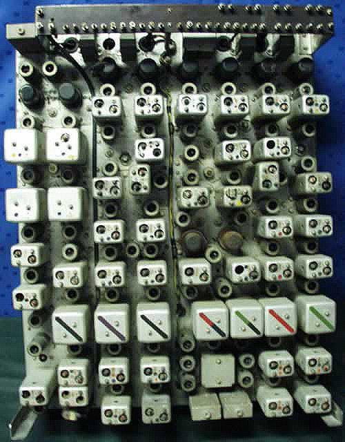
INTERNAL VIEWS OF THE MK XII DECOMETER BOWL
 |
| Mk XII decometer bowl with front bezel removed. |
 |
| Mk XII decometer - interior view. The biggest
decometer was used for Lane Identification. |
 |
| Identification markings on the rear of the
Red decometer, |
 |
| Red Decometer- sample 1 |
 |
| Lane Identification decometer - sample 2 |
 |
| Lane Identification decometer - sample 3. |
| All internal decometer bowl photos in this
table by Sture Nystrom |
Mk 13 EQUIPMENT
Not allocated in the series.
Mk. 20 RECEIVER
This was a receiver made by Norwegian STK under name ANARLOF .It used
a digital readout.
MARK 21 EQUIPMENT
 |
| Introduced in November 1969, the Mark 21 was the first receiver where
everything was contained in a single box unit. (Photo from the collection
of Walter Blanchard) |
DESCRIPTION
The Mark 21 was all solid state marine receiver designed for use with
Decca chains radiating Multipulse (Lane Identification) signals only. It
was intended as a replacement for the Mk 12 receiver. Receiver and display
was housed is a single unit; was suitable for bulkhead, deckhead or table
mounting. Different mains voltages could be accommodated with interchangeable
power unit modules. Power consumption using AC was 25 watts and 35 watts
for DC. It employed locked oscillators on all channels.
When used with a non-Multipulse (V-type) chain, only the decometers
of the Mark 21 receiver would be operative but not the Lane Indicator
(L.I) readout. The L.I. readout may appear to have been triggered
but the numbers displayed were meaningless. The Decometers, however, would
operate normally with the fraction pointers automatically taking up their
correct positions within the Lanes, but the receiver provided no independent
check on the counting action of the Lane and Zone dials. It was recommended
by the British Admiralty that in the absence of L.I. readings, it
was necessary to set the Lane and Zone dials by reference to other navigational
data.
Since the L.I. readings were not valid, possible confusion could be
eliminated by turning the L.I. dimmer anticlockwise to dim the L.I. display.
It was essential to keep the receiver operating continuously in order to
avoid loss of Lane or Zone count, especially if no external data was available.
For all practical purposes, the Mark 21 was a Multipulse only receiver.
When the Mark 21 receiver operated with a Chain designated MP but having
only two slave stations, the fraction pointer of the Decometer associated
with the 'missing' slave station would rotate continuously. Although this
Decometer was not used, it had to be referenced correctly to zero; failure
to do that would adversely affect the L.I. readings for the two patterns
to be used. To do that, the user followed a simple procedure outlined in
the operator's manual.
 |
| Mk 21 installation aboard Her Majesty's Yacht Britannia, now an exhibition
ship at Ocean Terminal, Leith, Edinburgh, Scotland. (Photo by
Santiago Insua) |
Mk. 22 RECEIVER
Prototype for submarine use. Based on Mk. 15 but with decometers and
switchable Lane Identification / Zone Identification meters.
Mk. 23 RECEIVER
A Mk. 19 receiver for land vehicle use. It was built into a Creeth container.
Mk. 24 RECEIVER
A Mk.18 receiver redesigned for small craft. It did not go into production.
The early 1980's were a critical phase in the history of the Navigator
system since it marked a point at which conflicting forces were converging
upon the company. The technology to improve the product was now coming
on stream, (ie new receivers and packaged stations), the expiry of Deccas
patents, affordable microprocessors, rival receiver manufacturers, GPS
and the fallout that resulted from the takeover of the company by Racal.
All this must have left the designers wondering what path to follow
and it seems that they chose to hedge a few bets and make a play for multi-input
receivers. In hindsight, this generation of product was probably the finest
that Decca Navigator made.
Mark 30 Receiver
The set is similar in appearance to the Mk 21. It has three dials on
the front, each marked from 0-1 with divisions of 0.1, subdivided to 0.01,
with an additional digital readout in the centre of each. A panel beneath
the dials swings down to reveal further controls, including chain selection.
The Mark 30 was a semi-microprocessor controlled receiver, which was introduced
in 1981 in response to recent developments in electronics.
Mk 30 receivers were first produced by (Decca Navigator in 1981 and
then by Racal Avionics Ltd from 1 April 1982. One of the features incorporated
into the design was cross chain fixing.
Dimensions: 14.76" x 16.8" x 11.8"
Mark 51 - Looking for info. Contact jerry.proc@sympatico.ca
Mark 52 - Looking for info. Contact jerry.proc@sympatico.ca
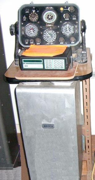
 |
Click on image for a description and additional
photos. (Photo by John Redpath) |
Mark 53
Click on image to enlarge.
 |
Mk 53G: No text available at this time
(Photo
by John Redpath) |
 |
Mk 53: This frontal view shows
the markings on the keypad. (Photo courtesy E-bay, Spain) |
 |
| Mk 53 rear view. (Photo courtesy E-bay, Spain) |
The MK53 was the last of the hyperbolic navigators, certainly
to be designed by what was the old Decca Navigator Company. The case
was used for many other products including the MK90 GPS receiver and an
Inmarsat marine telex system.
There was a significant thing about the case. It was the company's
first and only high pressure, die casting. Its tooling was very expensive
but it resulted in a case that cost less than £20 painted!
It was a lot cheaper that the sand castings used in MK21 and MK30 which
required extensive machining and preparation prior to painting.
Dimensions: 35cm W x 17cm D x 24cm H.
Weight: 5.25 Kg.
THE DEBUT OF THE MICROPROCESSOR IN RADIONAVIGATION
Sid Jones, who worked for Decca, explains some of the developments
which occurred in the area of microprocessor applications in radionavigation
receivers.
"As part of my post-graduate studies at Bangor University in North Wales.
I built a microprocessor controlled Decca Navigator receiver. My supervisor
was Doctor (now Professor) David Last, who had a good relationship with
the Decca Survey Company. After I graduated in Electronic Engineering in
1974, I was offered the chance to study the applications of microprocessors
in radionavigation systems.
We used an Intel 4040 microprocessor chip (all of 4 bits and 3 MHz!)
and produced a one-off receiver that used crystals to select various chains.
That explains the selector knob and the placard atop the case indicating
various chains and the values the synthesizer needed to order to generate
the range of frequencies for each chain.
The software detected the patterns of breaks in the signals to trigger
and meshed the pattern data to get zone and lane identification. Because
the zones had a built in ambiguity we used a 'flip' switch on the front
to toggle the zone setting. The display cycles round the red green and
blue patterns and streamed data output via a 20 ma serial interface.
This was tested successfully at sea and on land and was demonstrated
to a well known company in South London in 1976 who thought it was novel,
but had no further interest in it. As Decca Survey had sponsored my postgraduate
studies, I joined them in 1977 and was part of the team that developed
a microprocessor based HiFix/6 receiver which was a fraction of the size,
power and weight of the original. But, of course, that is an entirely different
story! "
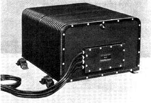
 |
| 1975: A prototype of a microprocessor controlled Decca Navigator
receiver designed by Sid Jones. (Photo by Sid Jones) |
Decca Navigator Simulator
 |
| E-bay photo by Tigerstime |
This nameplate, affixed to a Type 2538 decometer bowl for a
Mk XII system, suggests there was a training simulator. If anyone has any
information on it, please contact jerry.proc@sympatico.ca
MARINE AUTOMATIC PLOTTER
The Decca Marine Automatic Plotter (DMAP for short) provides an accurate
and continuous map presentation of a ships position and at the same time,
producing a complete record of the track made good. It enables ships to
follow any desired course with an accuracy hitherto unobtainable and eliminates
the problems which are encountered when a ship is required to make good
a track which does not coincide with a Decca hyperbolic position line.
Used in conjunction with the Decca Navigator receiver MK V or
with Decca Survey equipment ,this display unit is primarily intended for
operations in which accurate holding of predetermined tracks and the maintenance
of complete track records are essential.
In principle, the DMAP is similar to the Decca Aircraft Flight Log ;
the decometer information is translated into related movements of a roller-mounted
chart and a plotting pen along axes lying at right angles.
The hyperbolic Decca position-line patterns are presented upon the chart
in a rectilinear inverse lattice form; the pen indicates the position
of the ship upon that lattice at any instant, tracing a continuous record
of the track made good as the ship moves across the Decca pattern.
A range of five switch selected scales, from 0.25 inches to 4 inches
per Decca lane, is available for both the pen and the paper, thus giving
chart scales between 1:5,000 and 1:80,000 in the central coverage of a
Decca Chain. These limits fall to some 1:30,000 and 1:500,000 at the extremes
of the coverage area. Further switching gives four possible orientations
of the display each displaced 90 degrees from the next, enabling a rough
approximation to north - or heading-upward display to be obtained
in all parts of the coverage area. The remaining controls, in addition
to their use in setting up the display, provide facilities for producing
latticed charts on a blank chart sheet. This last operation permits
the production of track records in areas for which no prepared charts are
held, By entering the control settings and the decometer readings for any
one point on the track upon the chart , a complete record is obtained
.
The complete DMAP comprises of a display unit and Control Amplifier
(embodying the power supply) . The first houses the actual display head
in which an area of chart approximately 10 in. by 10 in. is visible at
all times along with the operating controls. Its equipped with a
glass, water-resistant cover , a quick release catch permitting easy access
to the chart and controls. The amplifier power supply unit takes
the form of a shelf or bulkhead mounted case. The equipment is designed
for operation from an AC power source and will normally draw its supply
from the converter associated with the Decca receiver.
 |
| Decca Marine Automatic Plotter (Decca Navigator Company photo) |
TRACK PLOTTER - MODEL 350T
 |
| The Decca Marine Track Plotter Model 350T was released by Decca in
in 1972. The 350T was the transistorized version of the Model 350. Click
on image to enlarge. (Image provided by Laval Desbiens) |
Credits and References:
1) Walter Blanchard <wblanch(at)ntlworld.com]
2) Danac Operating Instructions Manual, June 1979. Decca
Navigator, New Malden, Surrey
3) Extracts from Decca's Genealogy provided courtesy
Walter Blanchard, Royal Navigation Institute.
4) Stuart A Wolf <stuart.wolf(at)nats.co.uk>
5) James Morrison Decca photos. http://www.flickr.com/photos/jamesm/107572653/in/set-72057594120797676/
6) DECTRA marketing brochure published by the Decca Navigator
Company.
7) Denis Chouinard <denischouinard(at)enter-net.com>
8) Santiago Insua <hwasp(at)hotmail.com>
9) Matthew Parker <parkermat(at)hotmail.com>
10) David Jones <dsjjones(at)bellsouth.net>
11) Mk 30 info http://www.competition-commission.org.uk/rep_pub/reports/1987/fulltext/215c04.pdf
12) Mk IV receiver- Decca Navigator News June 1966.
13) Sid Jones <jonesthechip(at)logicmagic.co.uk>
14) QM3/4 photo - http://www.rnmuseumradarandcommunications2006.org.uk/QM3%20QM4%20PHOTO.pdf
15) Sture Nystrom <sture.nystrom(at)gmail.com>
16) Mark Ramsay [ramsaym1(at)yahoo.co.uk]
17) Laval Desbiens
Back to Decca Intro Page
July 9/24