![]() |
Decca Model 306 Signal Generator. These were used at the master stations to service the "Remote Monitor Receiver". The remote monitor was a modified MkV receiver, located about two to three miles from the station and connected to it by landline in such a way that the Decca signals could be displayed on the decometers in front of the watch keeper. A signal generator would also be held by the local marine service company who repaired shipboard Decca receivers. (Photo submitted by Santiago Insua <deccanavigator(at)mundo-r.com>) |
![]() |
Decca Model 336 Signal Generator. Does anyone know what this instrument for used for? Contact:jerry.proc@sympatico.ca. (E-bay photo) |
![]() |
Decca Model 870 Signal Generator. Built by GPDSI in the USA, it was similar to the 306 except it had a motor which controlled the Red/Green/Purple identification sequence. The red paint on the front panel meant it was consigned to the scrap heap but luckily it was salvaged just in time. (Photo by John Molloy-Vickers <vickymv(at)stn.net>) |
![]() |
|
![]() |
Model 8960B Signal Generator S/N 56. It was used in the mid-1960’s
and onwards as a bench test unit for the Mk15 to Mk19 range of Decca aircraft
receivers. It also marked the identification sequence with a
"hole" in the master transmission. This was a Decca system "feature" which was added to thwart a new crop of Decca compatible receivers after they came to market . The thinking was that this type of signaling would be incompatible with the crop of cloned receivers thus protecting Decca’s market share. The hole was added on an experimental basis to the English chain only by Rex Young. It worked, and the clones could not be easily modified to get around the problem. The 'B' version was the second and final type. Although it is enclosed
is a neat travel case, it was not really intended to be a field test unit.
Apparently it was designed to work with an 8961 monitor box. The device
in the photo was last calibrated in 1994 and is still in use in Spain by
Santiago Insua to demonstrate the principles of the Decca system. (Photo
by steve(at)engineroom.free-online.co.uk)
|
![]() |
|
![]() |
The 8961B is a special-to-type test set for the Mk 19 Decca Navigator only. It was designed for line testing of the Mk 19 receivers fitted to some Royal Navy choppers. It does not radiate RF any signals. (Photo courtesy Walter Blanchard) |
![]() |
Can anyone confirm if this RF signal generator was used on Decca's production line and if so, for what family of products? What is the approximate vintage? The nameplate is marked: The Decca Navigator Co. Ltd., Signal Generator, 20-40 Mc/s Type 162 Serial NO. 0031, Made in England. Click to enlarge photo. Photo submitted by Tobias. E-mail mongosapien(at)t-online.de |
![]() |
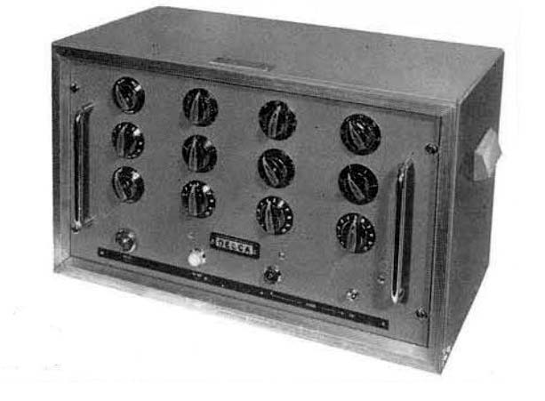
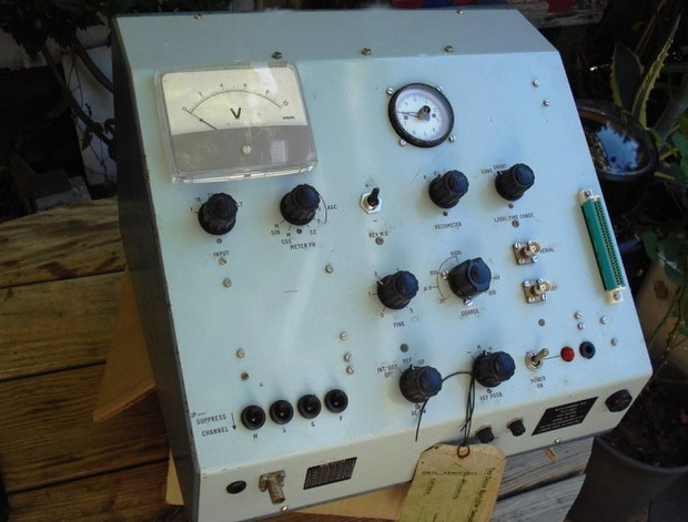
2536A Marine Simulator permitted marine navigation problems
to be illustrated and solved in a safe, repeatable, economic and instructive
way. For many years, Decca designed and supplied Navigator Marine Simulators
for classroom instruction. An example of one such simulator was the Type
2536A which was primarily designed to simulate the operation and
performance of the Mk. 5 and Mk 12 type Decca receivers. It had been provided
with calibrated dials which permitted local setting up of the meter readings
for both Lane Identification and Decometer indicators. This was of particular
value when the Decometer display unit was remotely situated from
the simulator. That allowed some flexibility in instructional methods.
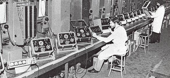
With the aid of this simulator, it was possible to demonstrate the shipboard use of the Decca Navigator System under classroom conditions and in locations where the reception of actual Decca transmissions would not be possible. By 1967, more than 70 Decca Navigator simulators were installed in nautical schools, Naval establishments and training centres throughout the world. (Photo and copy from Decca Navigator News, Spring 1967 edition) |
![]() |
Mk 12 ( left) and Mk 21 (right) equipment is being tested at Decca's Marine Service facility at Croydon, England in the early 1970's. There was a staff of 400 employed at this location. It included workshops, spares inventory, installation, service control, engineering support and training. (Courtesy Decca Navigator News April, 1972) |
![]() |
![]() |
The MS2A appears to be a Printed Circuit Board tester but its not known to which Navigator line it applies to. There is a small clue. In the lower left corner, the Channel Supressor switches are labelled M R G P which likely means Master, Red, Green and Purple THe Decometer switch is labeled R,G, and P. From a service tag, it appears the tester is circa 1976. (Photos by Blake Devitt) |
![]() |
Decca Navigator multimeter model 1940A. (Image via E-bay) |
![]() |
Model 9048 voltmeter. (Image by Dan Payne) |
![]() |
Model 9048 voltmeter nameplate. |
Credits or References:1) Walter Blanchard <wb(at)g3jkv.co.uk >
2) 80311B photos via Gilbert Hoste [gh841146(at)scarlet.be]
3) Dan Payne [paynepower4u(at)gmail.com]Oct 12/24