 |
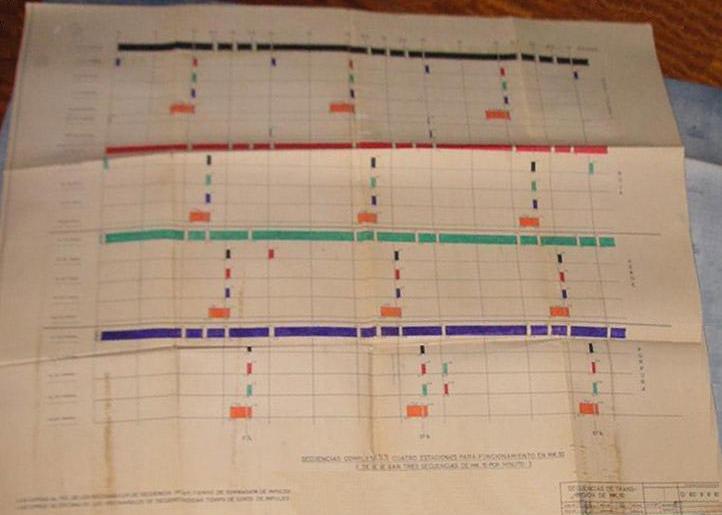
| This figure illustrates the 20 second transmission sequence for MP Decca Navigation chain. Hatched periods denote 8.2f transmissions for chain control and surveillance. (Graphic courtesy of The Decca Navigator Co) |
MULTIPULSE vs 'V' SignalsThe original Decca emissions were given a designation of 'V' mode transmission . V mode had two subsets, namely V1 and V2 , however no technical description is available at this time. In the fall of 1962, Decca introduced MP (Multi Pulse) signals. At first the MP chains were the exception rather than the rule, however by 1973 MP was referred to as a "normal" chain.
The MP system added the 8.2f transmission which was decoded and used as a coarse zone indicator (0.2f). This zone indication overcame the problem found by fast moving aircraft which could easily fly through lanes and thus needed a coarser indication of basic position. A slow moving vessel started out knowing their basic position. The 8.2f transmission was known by the name Orange. This was in addition to red, green, purple and black being the basic Decca chain transmissions. Since the 8.2f was not used for navigation purposes, it was used for sending chain data between stations and alarm signaling. In MP mode, alll the stations in each chain took turns radiating all five frequencies (5f, 6f, 8f, 8.2f and 9f) on a 20 second time interval.
The V was named after the standard marine receiver model of the period, this having the basic three decometer's and whole chain selection. Ground equipment and transmitters were the same for both formats, the only difference being the antenna coil assembly. Another benefit of the Multi Pulse upgrade was the ability to use sub-chain frequencies, (5A, 5B, 5C, etc), rather than the whole number chains that had been the norm. This allowed for chains to be positioned closer together with less chance of interference. The Mark-10 was probably the first Multi Pulse receiver and was also most likely and airborne one. The basic marine Multi Pulse receiver was the Mark-12 which lasted almost to the end of the system and was the basis for the system monitoring receiver.
|
| This figure illustrates the 20 second transmission sequence for MP Decca Navigation chain. Hatched periods denote 8.2f transmissions for chain control and surveillance. (Graphic courtesy of The Decca Navigator Co) |
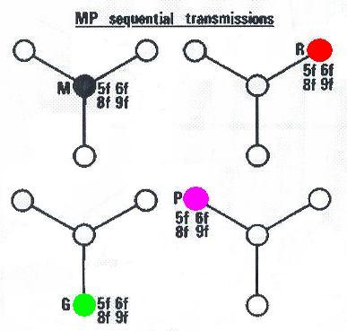
This diagram illustrates the transmitting order of a Decca MP chain. The sequence is M, R G, P. Although not shown here for clarity, each station also transmits 8.2 f. Please refer to the sequence diagram for 8.2f transmissions. (Graphic courtesy Decca Navigator Co. Modified by Jerry Proc)
This is the "linear" version of the transmit sequence chart. Click to enlarge. (Photo courtesy Santiago Insua, Spain).
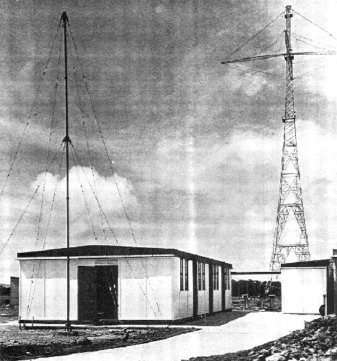
MAST RADIATOR AND GROUND RADIALSInitally, a Decca transmitting mast was self-supporting, made of galvanized steel and employed lattice construction. It's overall height was 325 feet and the base formed a square some 60 feet wide. Mounted near the top, were four, high level booms supporting the specially designed umbrella type aerial array. At the junction of the 75 foot long booms was a work platform. The mast itself formed part of the aerial system and was mounted on four insulators with concrete supports and foundations. Mast head lighting was also incorporated into the design. The height of the towers and the number of towers varied. At Alma Nova Scotia,. there were three towers but they were only 180 feet high.
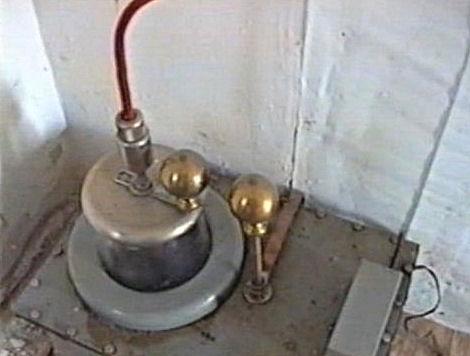
DECCA SLAVE SITE: This photo illustrates a typical slave site. At the left is the transmitter building. To its right is the ablution (washroom) building. The antenna in the foreground received the phase control signal sent by the master station thus providing input for the Phase Control Unit. Due to the distance and the contrast in the photo, the catenary of support cables is not visible on the main antenna tower in the background. (Photo source unknown) EARTH SYSTEM
A good earth system was necessary to ensure the high efficiency of the Decca Navigator transmitting station, hence an extensive pattern of radial earth wires was therefore employed
This system consisted of 90 radials. Each radial consisted of 7 gauge, 18 strand copper wire, 325 feet long. These were equally spaced radiating from the center formed by the Aerial Coil House. In some installations, these radials were laid above ground for the whole of their length and supported on light wooden posts extending about 18 inches above the ground. To reduce the area covered by the earth system and to free land for agricultural purposes, the radials were laid above the ground to the extent of the area covered by the mast and from that point the wires were buried about 18 inches below the surface.
MAST INSULATORS
Arthur O. Austin was the founder of the A.O. Austin Insulator Company of Barberton, Ohio. He was a prolific inventor in the early to mid 1900's and at one time is believed to have held 225 different patents for various insulator products. These achievements allowed him to lead the field in North America for the design and manufacture of Radio Frequency Insulators and Tower Lighting Transformers. Many radio engineers will recognize the renowned "Austin Ring Transformer", which was respectfully named after its inventor, A.O.
Austin. Through a succession of ownership changes, starting in the late 1960's, Austin Insulators became the Insulator Division of Decca, Racal-Decca, and then Litton Marine. In 2000, through an employee/management buyout, the Austin Insulators company emerged.. The new firm is now based in Mississauga Ontario.TRANSMITTERS -THERMIONIC TYPE
Each station was fitted with three continuous wave transmitters. One unit was always considered to be operational. Another unit was designated for "immediate standby" with filaments on and all ready to take over should the operational transmitter fail. The third was available for maintenance. With this arrangement, the standby transmitter could be flashed up in less than 1.5 seconds thus ensuring continuity of transmission.
TRANSMITTERS: Pictured here are two of the three original 2 kilowatt continuous wave transmitters. (Photo source unknown) In the mid 1940's, a completely new Decca Navigator transmitter had been designed which dispensed with the triplicate installation and at the same time gave absolute insurance against failure of transmission. This was known as the Decca Navigator Unit Type Transmitter. One complete transmitter consisted of eight power amplifier units and two drive units working in parallel to provide a transmitter output of 640 watts. Each unit was completely self-contained with its own power supply. Spare power amplifier and drive units were provided on-site so that any one unit could be withdrawn from the transmitter and replaced by a spare without interrupting the main transmission. This "unit principle" made it unnecessary to have complete standby transmitters and improved the efficiency of maintenance.
To provide a transmitter power output of 2.5 Kilowatts, a bank of four Unit Type transmitters, each giving 640 watts output, were arranged in parallel. Under typical conditions, the transmitter building was placed some 600 feet from the Aerial Coupling Coil which was housed directly under the aerial mast. On the English Chain, an open wire feeder system was used which consisted of two parallel Litz wires placed 3 inches apart, transposed at intervals and supported on insulators mounted on 10 foot wooden gantries spaced 30 feet apart. Alternatively, it was practical to also use suitable coaxial cable laid along the ground in shallow conduit.
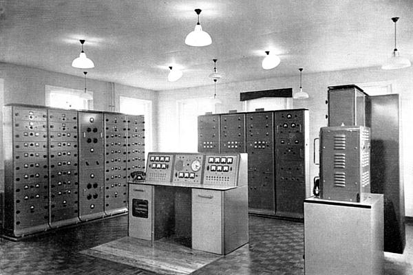 |
| A typical Decca station using 820 series equipment. The monitoring desk is in the centre.(Photo courtesy Decca Navigator Company) |
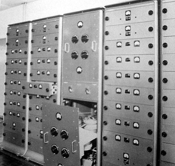 |
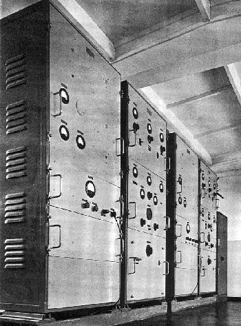
| Each of the four transmitter racks in a station contains ( top to bottom) two drive units in parallel. six power amplifier units, one spare power amplifier and one spare drive unit. Only three out of four racks are shown. Two of these racks provide the normal pattern transmission and two provide Lane Identification (LI). At this Purple slave, two pairs of LI transmitters are used. The central; rack contains the transmitter tank circuits and changeover switching. (Photo courtesy Decca Navigator Company) |
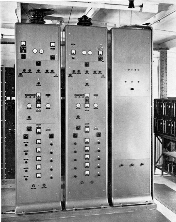 |
| Control racks of a Decca station. Though similar in appearance on all
stations, they perform a different function at the Master station from
that of the Slave stations. At each station the racks are provisioned in
triplicate. One serves as the "duty unit" one runs on standby, ready for
instant operation while the third is available for maintenance.
A Master Drive Rack contains: (i) A crystal oscillator of great stability which controls the station
frequency.
A Slave Drive Rack contains: i) A crystal oscillator forming the source of the slave signal.
|
SLAVE STATION PHASE CONTROL UNITTransmissions from the slave station are phase looked to the master transmission by the action of the Phase Control Unit (PCU). This unit is installed only on the slave stations. Its action is to receive the crystal controlled master transmission, provide a drive for the slave transmitter, and to phase lock the two transmissions by continuous comparison and automatic correction of the slave transmission as necessary.
In the English Chain., the following frequencies were used. Note how the slave frequencies are derived by multiplication and division of the Master frequency.
Master ............. 85.0 Kc/s
Green Slave.........127.5 Kc/s = 85 x 3/2
Red Slave ...... 113.33 Kc/s = 85 x 4/3
Purple Slave ........ 70.83 Kc/s = 85 x 5/6Each slave station also required a different comparison frequency to be compared with the Master frequency in the phase discriminator. These are as follows:
Green .... 255 Kc/s = 85 x 3 or 127.5 x 2
Red ........ 340 Kc/s = 85 x 4 or 113.33 x 3
Purple ..... 425 Kc/s = 85 x 5 or 70.83 x 6Associated with the Phase Control Unit on the slave stations was a 30 foot tubular steel mast and aerial for reception of the master signals. (See slave station photo above)
POWER SUPPLIES
The ground station equipment operated from a commercial 230 volt, 50 cycles per second, 3-phase power source which was rated at 11 kilowatts. That included heating and lighting requirements as well. Standby power could be derived from two 5.6 KVA diesel driven generators and one 22.5 KVA petrol-electric unit. One diesel generator was constantly running in readiness for immediate changeover. Diesel fuel was stored in a 600 gallon above-ground tank. Once the new Decca Navigator Unit type transmitter came into service it was possible to feed part of the equipment from the mains supply and part from a diesel driven generator with switching arranged so that one of these two sources of power would take over the full load in the event of failure of the other supply.
820 STATION EQUIPMENT
David Jones, a former Decca employee, describes the 820 station equipment. "The 820 generation of station equipment was probably the most widely deployed of all the Decca transmitters, but was tricky to maintain and when scrapped, had very little value to anybody. This type of station equipment was deployed on chains in the UK, Europe, Canada, Vietnam, Bahamas, North Spain, Persian Gulf, India and Bangladesh just to name a few. The photo set below shows a tank unit, a transmitter unit, a phase control cabinet and a RAMME/RASME rack, all looking as clean as the day they were taken out of service.
All photos in this block by James Morrison. These pristine examples of Decca transmitting equipment are found at the Port Ness Museum, at the top of the Isle of Lewis in the Hebrides Islands, Scotland. It is amazing how this equipment survived since it should have all been upgraded to the last generation of solid state, unattended units during the late 80's or early '90's. Perhaps these racks were donated to the local museum to show the island's strong links with Decca and the local fishing industry. Click to Enlarge 820 Equipment. From Left to Right:
* Transmitter tank unit. Matched the output of an individual frequency
transmitter to the feed line that went to the antenna coil system.
* Transmitter unit. Single frequency 1200 watt transmitter.
* Phase Control Cabinet. One of three identical units that provided the
phase locked, time synchronized output to the transmitter units. The basic
unit was similar at both master and slave stations, the only difference
being that the master station unit had a master oscillator as the
transmitter frequency standard whereas the slave station units had a 6F
receiver which was used to lock their own oscillators. Both versions used a frequency locked clock unit to provide the timing and switching signals
needed. The lower part of the rack had the five individual frequency output
stages and their respective phase adjustment goniometers.
* RAMME/RASME. The main control and supervision unit that allowed the station to run with minimum supervision.Shows part of the RAMME/RASME front face with the indicator
lamps for each PCC (Phase Control Cabinet). The switches are used to select a duty PCC and also perform routine maintenance by taking a PCC out of service. Typically, only one amber light would be on; that of the in-service PCC.The lower section of the PCC and the adjacent RAMME/RASME. This lower section of the Phase Control Cabinet housed the five individual output stages. The front panels of al these racks could be easily
removed with a few screws to reveal the tubes and tuning coils inside. There was no need to remove any of the front adjustment knobs, the panel just lifted off over them.Antenna ammeters from the coil house. They were placed on the floor of the coil house, just as they are shown, with the phase loop transformer behind them. Normally mounted on a board, they would be situated to the side of the coil trestle, very near the center. The end of the C-coil winding would be passed through the phase loop transformer and then be grounded via the thermal ammeter, seen here on the right. The C-Coil was the main coil connected to the antenna. Hence the two ammeters provided a good indication of antenna current, one read via a DC rectifier, the other by opening the attached knife switch on the thermal ammeter. TANK UNIT
The tank unit, far left is designed to match the transmitter to the antenna feeder cable. Each tank cabinet houses two tank units, one for each transmitter. Originally, only one cabinet would have a single tank module fitted until the deployment of an 8.2f transmitter made up a full set. The transmitter rack housed six individual amplifiers and two driver units. Each amplifier had six, type 807 PA valves (tubes), fed from a 750 volt DC anode rail. When first tuning up a station, we would remove five of the amplifier modules and by keeping the driver unit just unscrewed past its micro-switch, could switch the amplifier on and off as needed. Later, if no sparks were seen at the coil house, we would add more amplifiers to bring the power up on each band.
PHASE CONTROL
The Phase Control Cabinet was a marvel of relays and RF. At the top of the cabinet was a clock, driven by the rack oscillator which was in turn locked to a 6f receiver channel. The clock was the key to the sequence and it had a rotating arm with a magnet that passed a band of reed relays arranged around its circumference. As the reeds closed, so they activated a main set of relays, all mounted on a hinged panel, behind the clock unit at the top of the rack.
Further down was the 6f receiver unit and its station goniometer. Next came the oscillator unit and then the lower section of the rack was the four (or five) frequency channels, each with their own output goniometers. To tune up an 820 station, we would first stop the clock at the exact station indent when all the transmitters were being driven and the coil house clanger relays were energized. Stopping the clock at the exact indent took a bit of practice but with a careful ear, it could be done. After first removing the transmitter drivers, it was now possible to switch each frequency to the antenna coils, using the clanger relays in the coil house.
The clangers were the name given to the big dual pole relays in the coil house that switched the antenna de-tuning windings in during the quiet period (to prevent re-radiation), and then energized during the identification phase. Their 80 volt return circuit was used to key the transmitter, so by having the rack stopped on the identification and the transmitter on, you could be alone in the coil house and send RF up the stick by plugging each clanger in and out. The relay itself was about six inches square and had a handle on the front that made it ideal for the task. In many strange and foreign lands, this method of tuning was invaluable since a technician would often be working on his own and had little confidence in the local staff or their ability to understand your requests. Since the technician was the one at the sharp end, there had to be some foolproof way of controlling the RF and this proved ideal.
RAMME/RASME
The RAMME/RASME (Remote Automatic Master monitoring Equipment or Slave Monitoring Equipment was a single rack that used a three way vote to decide the operational status. All the rack alarm functions were fed to this unit and by monitoring them it decided if the duty rack should be changed based on a vote. The amber lamps on the front show the status of each PCC rack and from top to bottom they went from In service, Dubious, Suspect, No-vote and Out of service. Basically, it monitored minor and major alarms to decide on the action to take. Using the RAMME/RASME, any of the three PCC racks could be taken manually out of service for repair. At the top of the rack is a collection of amber alarm lamps that latched on to record system status and had to be manually re-set to clear.
OSCILLATOR (not shown)
As a system upgrade, Decca incorporated a rubidium standard oscillator control unit, which was designed to counter the effect of skywave by having a highly stable frequency standard at each station. Each station used three Hewlett Packard rubidium standards, each mounted inside a controlled temperature cabinet and the whole thing was monitored and switched by the blue colored unit. It is doubtful how much improvement was made by this but it did remove one component of the system error by keeping the station on a locked and stable phase source".
MATCHING UNIT
 |
| This model 2951 matching unit was used for frequency 5F. It's part of the abandoned Decca equipment the 7B Green slave in Højer, Denmark. Plug-ins at the right side of the rack have been removed at time of de-installation. 7B was the second Decca chain that was built. (Photo by Santiago Insua) |
 |
| This .005 uf., 6000V capacitor was found in the secondary coil house at the abandoned 7B Green station. Its size can be gauged approximately by comparing it with the crushed beverage can at the bottom centre of the photo. (Photo by Santiago Insua) |
820 EQUIPMENT PHOTOS
All captioning provided by David Jones. (All photos in this block by James Morrison)
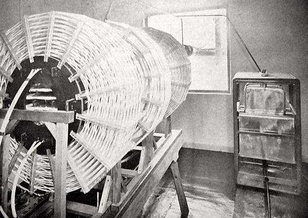 |
| Coilhouse: This is the aerial loading coil and the air spaced tuning condenser used in a Mk V purple slave. (Photo courtesy Decca Navigator Company) |
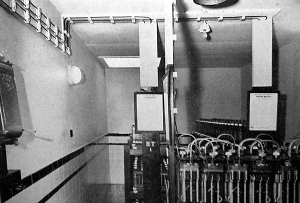 |
| The emergency batteries could provide sufficient power to operate a station on full load for about 40 minutes. This could be extended to 4 hours by switching off all unessential equipment and reducing the power output of the transmitter. Normally the load would be transferred to the standby generator so the battery bridges the time gap until the generator becomes available. (Photo courtesy Decca Navigator Company) |
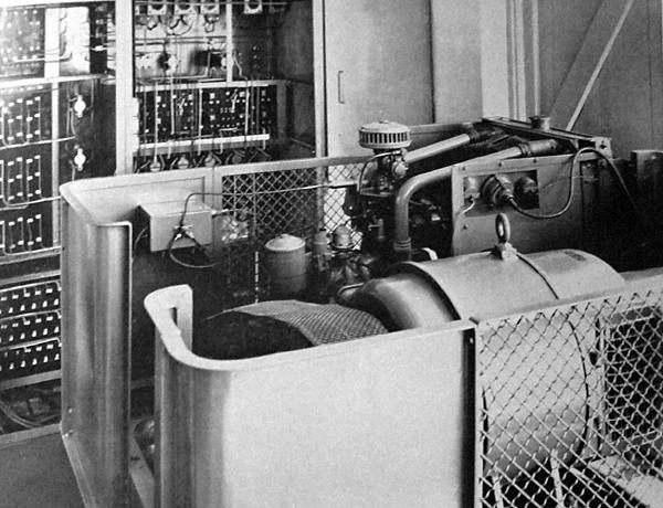 |
| A typical gasoline-driven standby generator which was used in the event of a mains failure. Standby generators were standard equipment on all Decca stations and were rated to supply the full load requirements of the station continuously. In many cases these sets were equipped with an auto starting feature which would bring them into service within 10 seconds of the mains failure. (Photo courtesy Decca Navigator Company) |
1880 EQUIPMENT
Select this link for information on 1880 series equipment.
MONITOR STATIONSThe operation of the slave station Phase Control Unit maintained the stability and accuracy of the system by means of automatic phase locking to the master transmitter thus eliminating the need of continuous monitoring as was necessary in other navigational systems. On the English Chain, however, Monitor Stations were set up for research and measuring purposes and to provide constant cross-checking of the operation of the chain in its early stages.
As a general rule of thumb, experience had shown that placing a human at the station often led to more problems since they had a tendency to dabble with the equipment when in reaity, it was best left alone. Most staff were excellent and their dedication was exemplary. A few just got bored and started fiddling.
MODERN TRANSMITTER EQUIPMENT - SOLID STATE
One of the major technical innovations in Decca transmitters was to make them fully automatic and be controlled by remote control. By eliminating manned sites, considerable costs savings could be achieved. Please refer to the block diagram of the last generation Decca transmitter. This diagram was developed by Väinö Lehtoranta, OH2LX. This drawing is based on the following originals:
- Technical Manual 13.1 (Dated Dec.67)
- Technical Manual 13.4 (Chapter 1 - dated Jan.73)For this specific station site, the tower was a radiator along with two horizontal wires supported by masts on either side, the purpose of which was to increase the capacitance hat. The main mast was 50 meters in height and the spacing to the outer masts was 100 meters. Many sites only used a radiating mast.
The brown arrows from transmitters 6f-9f each had their own connection to the coil system as shown on 5f. It was likely drawn this way for clarity. Feed circuits from each individual matching unit went to all five coils on the trestle.
 |
| Marked as a product of Decca Navigator, London, this solid state monitoring
receiver was used in master station of chain 7B Samsø
Island. Denmark. This equipment has now been been donated to the Museum
of Trade and Marine in Castle Kronborg, Elsinore Denmark. (Photo via
Hans Elfelt Bonnesen)
This is a chain control and monitoring unit from the last generation of chain equipment as evidenced by the LCD decometers in the top and the individual station status lamps in the section below. The last generation equipment was designed to run in full automatic mode with the ability to be accessed from a central location that could issue commands and receive data from the transmitter site. |
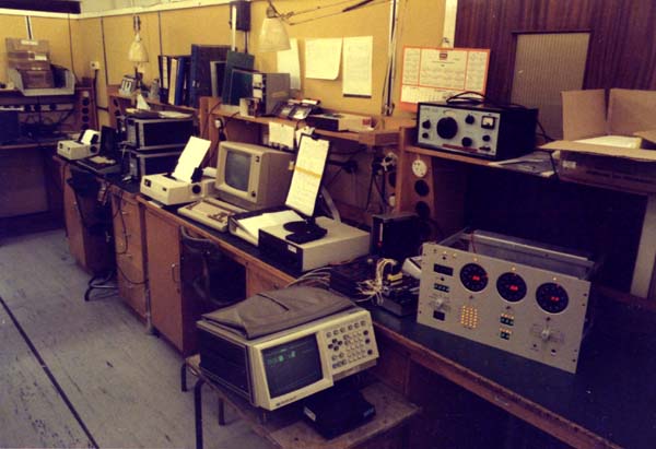 |
| In the lower right hand corner is a an LED decometer panel which is part of a solid state Decca Monitor Receiver. It was of the same type used at the UK Chain monitoring center in Edinburgh. Here, an example sits on the bench in Arthur Watt's lab at New Malden. Some of these receivers were also installed in a back-up control center at the Racal/Decca labs. (Photo from the collection of Mike Bennett ) |
ANTENNAS and TOWERS
Antennas and towers used in Decca chains can be broken down into these types:PYLON TYPE MAST
 |
This is an example of a pylon tower from the Puckeridge station of the English chain. It is believed that pylon type masts were only used in the English Chain. Click to enlarge. (Photo via Walter Blanchard) |
 |
| One leg of a pylon type mast showing the insulator and the lightening spark gap arrestor. Decca towers used insulators made exclusively by Austin Insulators. (From the collection of Walter Blanchard) |
For additional details about the A.O. Austin Company, select this link.
SINGLE TRIANGULAR LATTICE MAST
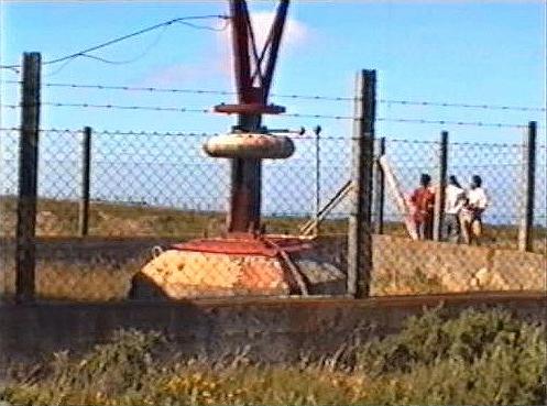 |
| More typical was the single triangular lattice mast, 300 ft tall, resting
on a single insulator and set on a raised concrete block. This example
is from the 4C chain.
The mast would be supported by two or three sets of guys, each one made up of insulated sections of steel cables. The mast base insulator would have a spark gap fitted and often a second spark gap just inside the coil-house window, directly below the feed-through. In general, the maintenance and performance characteristics of the single 300 ft lattice made it the de-facto standard. (Photo from video by Santiago Insua) |
 |
| Here is variation of the center supported tower at the Master station of the Spanish chain 4C at San Xoan de Rio. (Photo from video by Santiago Insua) |
 |
| Coil house spark gap lighting arrestor. (Photo from video by Santiago Insua) |
SINGLE WIRE 'Tee' ANTENNA
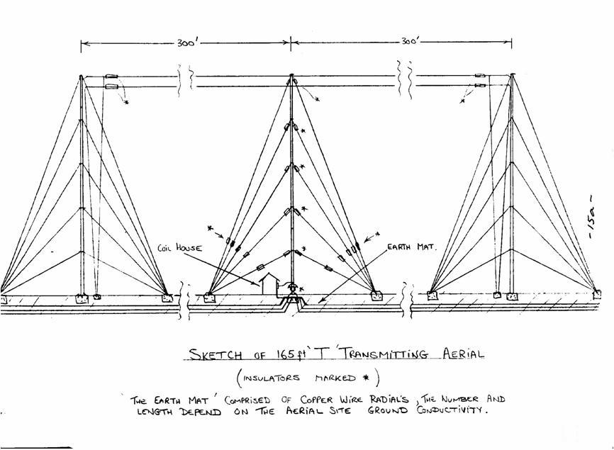 |
Other mast systems deployed were single wire 'Tee' antennas around 150 feet tall. Click to enlarge. (Image courtesy Decca Navigator Company from the collection of Walter Blanchard) |
TUBULAR MAST
 |
| This tubular mast was used at the 4C Purple station at Vitgudiono Spain. (Photo from video by Santiago Insua) |
One example of a guy wire insulator. (Photo from video by Santiago Insua) ANTENNA CURRENTS
The RF fields present in a 1.2kW Decca LF system had much in common with higher powered systems. You would think that a kilowatt or so would not be too difficult to deal with but perhaps because of the frequencies involved it becomes an issue. Also, any energy not being fed into the antenna was lost and hence all efforts were made to maximize the overall efficiency of the system. Any CW system can be hazardous to work with and the RF fields surrounding the Decca antenna system could generate substantial voltages. Typical RF antenna currents varied from 15 to 30 amps, depending upon the station frequency and at identification time the combined current pulse was in the order of 50 to 60 amps. This was measured at the tail end of the main antenna coil, just before it connected to the ground plane.
TUNING THE STATION
David Jones has complied a document that details the steps and procedures for tuning a Decca station and getting it on the air. These are based on his recollections from performing this task at several sites during during his time with the company. It may shed some light on the mystery that used to surround this secret process. For an outside observer, the process seemed to be tedious and boring since there was very little to see, just a continuous sequence of measurements and minor adjustments. The procedure is documented here.
Additional References and Credits:1) Austin Insulators http://www.austin-insulators.com/profile/index.html
2) James Morrison http://www.flickr.com/photos/jamesm/107572653/in/set-72057594120797676/
3) Santiago Insua <hwasp(at)hotmail.com>
4) D. Jones <dsjjones(at)bellsouth.net>
5) Walter Blanchard <wb(at)g3jkv.co.uk >
6) Hans Elfelt Bonnesen <hans.elfelt(at)me.com>Oct 19/11


