Loran-C transmitters are organized into chains of 3, 4 or 5 stations.
Within a chain, one station is designated "Master" (M) while the other
"Secondary" stations identified by the letters W, X, Y and Z. Different
secondary designations are used depending on the number of station in a
chain. This is summarized in the table below.
|
|
|
|
| Master with 5 secondaries | M V, W, X, Y, Z | South Central U.S. 9610 |
| Master with 4 secondaries | M W, X, Y, Z | Southeast U.S. 7980 |
| Master with 3 secondaries | M X, Y, Z | Canadian West Coast 5990 |
| Master with 2 secondaries | M W, X | Calcutta 5943 |
| Master with 2 secondaries | M X, Y | East China 8390 |
By 1989, there were 16 Loran-C chains comprising 67 stations and transmitting on 100 kHz. In the year 2000 this had grown to 28 chains. Power levels can range from as low as 11 Kw (Bombay 6042) to as high as 1.2 megawatts (China East Sea 8390) . In Russia, a navigation system known as CHAYKA is compatible with Loran-C hence it forms part of the workwide chain. Transmitting station signal availability is greater than 99.9 percent while typically providing 99.7 percent triad availability.
The Loran-C navigation signal is a carefully structured sequence of
brief radio frequency pulses (Fig. 1a) on a carrier wave centered at 100
kHz. All secondary stations radiate pulses in bursts of eight, whereas
the Master signal, for identification purposes, has an additional ninth
pulse burst (Fig. 1b). The sequence of signal transmissions consists of
a pulse group from the Master (M) station followed at precise time intervals
by pulse groups from the secondary stations. The time interval between
the reoccurrence of the Master pulse is called the Group Repetition Interval
(GRI), see Fig. 1c. Each Loran-C chain has a unique GRI.
 |
|
|
Since all Loran-C transmitters operate on the same frequency, the GRI is the key by which a receiver can identify and isolate signal groups from a specific chain. In naming the chains, the GRI is included. As an example the Great Lakes chain has a GRI of 8970. This means the time interval is 89700 microseconds. The rightmost zero is always implied and the GRI is always in multiples of 10 microseconds. In old Loran-C receivers, the operator had to actually set this number to receive the chain. In cases where the Loran signals were observed on an oscilloscope, pulses from the desired chain would be stationary while those from other chains would be drifting down the time base at varying speeds. It was in fact, the only way of positively identifying a chain, however in modern receivers, this is now done automatically.
GRI's are chosen on the basis of :
(a) Baseline lengths between master and secondaries. If the distance
between the
master and first secondary is say 1000 kms,
the radio signal will take 33,000
microseconds to get to the slave so the GRI
cannot possibly be less than that.
(b) Number of slaves that have to be accomodated - they all have to
have delays so
that there is no possibility of them
crossing over anywhere in coverage area..
(c) Geography.
(d) Other nearby chains witrh consideration given to interference.
(e) Skywave cross-rate interference.
(f) Duty cycle of the transmitters - a faster GRI means the average
power of the
transmitted signal is higher so the final
stage in the transmitter requires more
cooling.With average baseline lengths and
three slaves, the minimum GRI cannot be
much less than 50,000 microseconds.
 |
| Each Loran-C pulse has an approximate duration of 200 µs. The interval between pulses within a pulse group is 1000 µs, except for the last two pulses at the Master which have a 2000 µs interval. The graphic below illustrates one pulse. (Graphic Courtesy of NELS) |
 |
| This graphic illustrates the points on the Loran-C pulse envelope that define the start time, the time of maximum envelope power and the stop time of the pulse.(Graphic courtesy of NELS). |
Two other important characteristics are associated with Loran-C signals, namely emission and coding delay. If the master station is taken as a reference, the emission delay refers to how long it takes before the secondary transmits after the Master has done so. The coding delay is a very small correction that removes the local (near-field) discrepancy between the envelope and carrier. Both parameters are measured in microseconds and are uniquely associated with each secondary station.
BASELINES AND COVERAGE
An imaginary line drawn between the Master and each secondary station is called the baseline. The continuation of the baseline in either direction is called a baseline extension. Typical baselines are from 1200 to 1900 km (say 600 to 1000 nautical miles). Chain coverage is determined by the power transmitted from each transmitter in the chain, the distance between them and how the different transmitters are oriented in relation to each other (the geometry of the chain).
SKY WAVE REJECTION
A frequency of 100 kHz was chosen for the Loran-C carrier wave to take
advantage of propagation of the stable ground wave to long distances. However,
the presence of delayed sky waves, reflected from the ionosphere, cause
distortions of the pulse shape and change the carrier phase within the
pulses of the received signal. Not only that , the skywaves take longer
to arrive at the receiver than the ground wave, so their presence
complicates the computation. To avoid sky wave contamination, the Loran-C
receiver selects a zero crossing of a specified carrier cycle at the front
end of the pulses transmitted by master and secondary stations. Making
the cycle selection early in the ground wave pulse - usually the third
cycle is employed - ensures that the time interval measurement is made
using the uncontaminated part of the pulse. But how is the third peak selected
when the start time of the pulse is not known? To solve the problem, the
receiver compares the the envelope (the rough shape) of the received pulse
with a stored envelope, This process is called the "rough measurement".
When the third peak is finally located, the phase of the signal can
be determined. The phase of the signal can be zero or pi radians.
Precise control over the pulse shape at the transmitter also ensures that
the selected zero crossing can be identified reliably by the receiver.
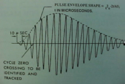 |
| Zero Crossing: This diagram illustrates the third cycle in the Loran pulse. (Graphic courtesy of the USCG). |
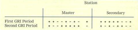
PHASE CODING
To reduce the effects of interference and noise on time difference measurements,
and to assist in distinguishing between master and secondary stations,
the carrier phase of selected transmitted pulses is reversed in a
predetermined pattern. The pattern is shown in Fig. 2, where a minus sign
indicates an inverted pulse (180° phase shift), and a plus sign means
no phase shift. This pattern is repeated every two GRI's. Simply stated,
phase coding determines whether the first peak in the pulse is upwards
or downwards.
 |
|
|
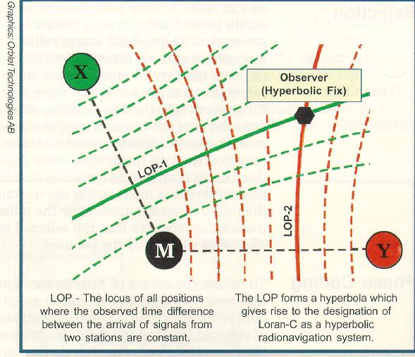
TIME DIFFERENCE MEASUREMENTS
The basic measurements made by Loran-C receivers are to determine the
difference in the time-of-arrival (TD) between the master signal and the
signals from each of the secondary stations of a chain. Each TD value is
measured to a precision of about 0.1 microseconds (100 nanoseconds) or
better. As a rule of thumb, 100 nanoseconds corresponds to about 30 metres.
The principle of time difference measurements in hyperbolic mode
is illustrated in Fig. 3.
 |
|
|
AUTOMATIC OPERATION
Todays state-of-the-art, solid state Loran-C transmitters are adapted for automatic operation; that is to say all vital transmitter functions are duplicated or designed for graceful degradation so that the result of a defect is minimised.These vital functions are further monitored at the Control Centre which has the capability of initiating corrective action using data communications. As a consequence, the transmitters may be operated as unmanned stations except for caretakers.
PRECISION CLOCKS
To achieve high positioning accuracy within the service area, Loran-C transmitter stations are equipped with a suite of atomic clocks which provide the timing for the transmitted Loran-C signal. On most stations these clocks are cesium frequency standards with a stability of typically 10-13, or an error of 1 second in 317,000 year. Precise navigation with Loran-C demands that the error in the timing system must not exceed a few tens of nanoseconds. For NELS it is specified that a station's clock shall not deviate by more than 30 nanoseconds from the clocks of the neighbouring stations. Achieving this precision in timing it is necessary to continuously measure the time deviation between the clocks in the system.
SAM CONTROL
There are two basic methods in use for monitoring and adjusting the clocks in Loran-C systems. The most commonly used method up to now is to measure the time difference between Loran-C signals received from a master and a secondary at a fixed location in the coverage area. Timing control includes making adjustments to the clock of the secondary station so that the measured TD is kept at a predetermined value. The measurement equipment at the fixed location is called a System Area Monitor (SAM), hence this method of timing control is referred to as "SAM control".
TOE CONTROL
In the other method for timing control, used by the Northwest European Loran-C System (NELS), there are no SAM's. Instead, arrival times of signals from adjacent transmitters are measured relative to the local clock at each transmitter station. The measurements from all stations in the system are sent by permanent data link to the control station where they are combined so that the time deviation of each transmitter's clock can be calculated. Computed adjustments are returned to the individual transmitter sites where they are used for clock synchronization. This results in a common time reference for the Time Of Emission (TOE) of the Loran-C pulses from all transmitters and is called "TOE control". The common NELS time reference is itself related to UTC using the UTC (Brest) time standard which is co-located with the NELS Control Centre at Brest, France. The NELS time reference synchronization to UTC (Brest) is maintained to within 100 ns.
TOE and SAM CONTROL COMPARED
Under TOE control, the time difference measurements over the coverage area will vary slightly with seasonal changes in the speed of ground wave propagation. With SAM control, time difference measurements made especially close to the area monitor will be very stable. TOE control thus provides better overall performance monitoring throughout the coverage area. Other advantages of TOE control over SAM control are:
* Modeling and prediction of TD variations are made easier.
* Time derived from the signals is more accurate.
* Better accuracy for cross-chain and master independent use.
* Better accuracy for Rho Rho navigation (circular navigation method);
* No monitor sites are needed.
ADDITIONAL SECONDARY FACTOR (ASF)
A Loran-C receiver computes distances from Loran-C transmitting stations using the time of arrival measurements and the propagation velocity of the radio ground wave to determine position. Small variations in the velocity of propagation between that over sea water and over different land masses are known as the Additional Secondary Factor, or ASF. Corrections may be applied to compensate for this variation. Such corrections may improve the absolute accuracy of the Loran-C service in positions where the received Loran-C signal passes over anything but sea water on its way from transmitter to receiver. The values of ASF depend mainly on the conductivity of the earth's surface along the signal paths. Sea water has high conductivity, and the ASFs of sea water are, by definition, zero. Dry soil, mountains or ice generally have low conductivity and radio signals travel over them more slowly, giving rise to substantial ASF delays and hence degradation of absolute accuracy.
Fortunately, ASFs vary little with time, and it is possible to calibrate the Loran-C service by measuring ASF values throughout the coverage area. A program for mapping of ASF in northern Europe is the basis for the production of ASF corrections. These corrections will be distributed as electronic databases.
SERVICE INTEGRITY
Loran-C stations are constantly monitored to detect signal abnormalities which would render the system unusable for navigation. "Blink" is the prime means by which the user is notified that the transmitted Loran-C signal does not comply with the system specifications. Blink also indicates that the Control Centre cannot ensure that the signal complies with these specifications, for instance, as a result of discontinuation of data communications linking the Control Centre to the stations. Blink is a distinctive change in the group of eight Loran-C pulses that can be recognized automatically by a receiver so the user is notified instantly that the Loran-C chain blinking should not be used for navigation. Blink starts at a maximum of 60 seconds after detection of an abnormality. Automatic blink initiated within 10 seconds of a timing abnormality may be added where Loran-C is extensively used for aviation purposes.
ACCURACY
The Loran-C service will support an absolute accuracy varying from 185 meters to 463 meters (0.1 to 0.25 nautical miles), depending on where the observer is within the coverage area. Absolute accuracy defines a user's true geographic position (latitude and longitude). Repeatable accuracy is a measure of an observer's ability - by using a navigation system such as Loran-C - to return to a position visited previously using the same navigation system. Loran-C repeatable accuracy is sometimes as good as 18 meters and is usually better than 100 meters within the coverage area.
PROPAGATION ANOLOMIES
The inherent accuracy of the Loran-C system makes it suitable for many land radio location applications. However, propagation anomalies may be encountered in urban areas caused by the proximity of large man-made structures. Compensation for these anomalies is usually possible either by prior measurement or by the application of the local ASF. Substantial improvement in the accuracy of Loran-C service is technically possible by the measurement and broadcast of local corrections in a technique known as differential Loran-C (DLoran-C). This is similar to what is achieved with GPS using GPS differential corrections known as DGPS.
TIME TRANSFER STANDARD and OTHER MODES
The Loran-C system is capable of being utilized as a time transfer standard.
The HF stations WWV and WWVH (and others like CHU) suffer from variations
in propagation time because of changes in the ionosphere. WWVB at
60 kHz is much better in that respect but suffered from low output power
until the late 1990's. Loran-C was the best source of radio time signals
for the last few decades. A number of companies built receivers that
were specifically designed to be time reference receivers.
It's only been in the last few years that GPS based time transfer had
better performance than Loran-C. Apparently, there is a capability to send
digital data on the Loran-C signal for military use. Can anyone comment
on this?
LORAN-C can be utilized in different modes of operation. Most common is the hyperbolic mode. Circular mode, often referred to as Range-Range or RHO-RHO, has limited application for special users. Unique and expensive user equipment is required for RHO-RHO operation however, it only takes a fix from two stations to establish position.
SIMULATED LORAN-C SIGNAL