OMEGA
By Jerry Proc VE3FAB
INTRODUCTION
The OMEGA radionavigation system, developed by the United States Navy
for military aviation users, was approved for full implementation in 1968
and promised a true worldwide oceanic coverage capability and the ability
to achieve a four mile accuracy when fixing a position. Initially, the
system was to be used for navigating nuclear bombers across the North Pole
to Russia. Later, it was found useful for submarines.
When the eight station chain became operational, day to day operations
were managed by the United States Coast Guard in partnership with
Argentina, Norway, Liberia, France, Japan and Australia. Coast Guard personnel
operated two U.S. stations - one in LaMoure, North Dakota and the other
in Haiku, Hawaii. OMEGA employed hyperbolic radionavigation techniques
and the chain operated in the VLF portion of the spectrum between 10 to
14 kHz. Near its end, it evolved into a system used primarily by
the civil community. By receiving signals from three stations, am Omega
receiver could locate a position to within 4 nm using the principle of
phase comparison of signals. In the Royal Canadian Navy, the OMEGA system
was used in the AOR, 280 and Halifax class ships.
HISTORY
John Alvin Pierce, the "Father of Omega," first proposed the use of
continuous wave modulation of VLF signals for navigation purposes in the
1940's. Working at the Radiation Laboratory at the Massachusetts Institute
of Technology, he proved the viability of measuring the phase difference
of radio signals to compute a location solution. Pierce originally called
this system RADUX. After experimenting with various frequencies, he
settled on a phase stable, 10 kHz transmission in the 1950's. Thinking
this frequency was the far end of the radio spectrum Pierce
dubbed the transmission "Omega," for the last letter of the Greek alphabet.
Radux-Omega showed the possibilities of very-low-frequency propagation,
but there were fears about ambiguity errors if a single low frequency were
used on its own. In the 1950's two new factors appeared - the inertial
navigation system (INS) and the great increase in electronic system reliability
following the introduction of the transistor. INS was not all that accurate,
particularly in ships, where it had to run for days on end without correction,
but it could certainly carry over short losses of signal and resolve any
cycle slippage that might have occurred, while better reliability meant
that such outages were far less likely anyway.
Thus, ambiguities might be much less of a problem than thought, and
the development of a single frequency system began to seem feasible. The
40 kHz of Radux was dropped and a new system using transmitters in California
and Hawaii was set up, transmitting at 12.5 kHz. They provided good results
and two further transmitters were added in Panama and the Post Office station
at Criggion, North Wales. All these stations ran on their own time standards,
the development by Dr L. Essen of the National Physical Laboratory. This
new type of extremely stable crystal oscillator, named after him, made
this progress possible. Later, Dr Essen also built the first cesium beam
atomic resonator.
These experiments continued throughout the 1950's and provided a great
deal of data on propagation characteristics. Nothing that was found discouraged
the idea of a navaid operating at low frequencies. In 1963, an Omega Implementation
Committee (OIC) was formed chaired by Prof. Pierce and consisting of most
of those who had been concerned with the earlier experiments. They were
charged with designing the new navaid and, on the basis of their experiments,
took the decisions about how Omega would work - the choice of frequencies,
location of transmitters, power levels, etc. Originally it was calculated
that a 10 KW power level from each transmitter would prove more than sufficient
for reliable reception. Due to the high cost of constructing VLF antennas
(Omega antenna towers were more than 1,200 feet in height), the first experimental
transmissions were actually existing VLF communications stations that were
modified for Omega transmissions. This committee always denied later that
the Decca work on Delrac, disclosed 9 years earlier, had had any effect
on their deliberations, but it was interesting that they chose identical
frequencies and other characteristics.
Over 31 possible transmitting sites were considered. Eventually, eight
locations were established as permanent transmitting stations. The Bratland,
Norway station (near the Arctic Circle) and the Haiku Valley station on
Oahu, Hawaii, originally experimental stations, were among the first in
the system. In 1968, the U.S. Navy authorized full scale implementation
of the Omega System based on the OIC report. Responsibility for the operation
was transferred from the U.S.Navy to the U.S. Coast Guard in 1971, under
the terms of title 14, USC 82. The Coast Guard created a new command, the
Omega Navigation System Operations Detail (ONSOD) to operate the system.
ONSOD control of the synchronization of the system was perfected while
the Navy Project Office finished the task of constructing the stations.
As construction of the final six stations proceeded through the 1970's,
ONSOD assumed the duties of engineering maintenance for those stations
as they were declared operational. Eventually, eight permanent stations
located in Bratland, Norway; Paynesville, Liberia; Kaneohe, Hawaii, US;
La Moure, North Dakota, US; Plaine Chabrier, La Reunion, France (Indian
Ocean); Golfo Nuevo, Chubut, Argentina; Woodside, Victoria, Australia;
and Shushi-Wan, Tsushima Island, Japan were completed.
Separate bilateral agreements were negotiated between the U.S. and the
six partner nations. ONSOD, later the Omega Navigation System Center (ONCEN),
was named the Operational Commander (OPCON) with each partner nation maintaining
responsibility for administrative control (ADCON). The U.S. owned and maintained
all the Omega related equipment at each station. The host nation provided
personnel, funding and non-Omega support for the station. Partner nation
crews came from military and civilian sources. The Argentine and French
stations were crewed by both military and civilian members of their respective
Navies; the Japanese station was crewed by uniformed members of the Japanese
Maritime Safety Agency, while the Australian station were staffed by civilian
employees of the Maritime Safety Agency (equivalents of the U.S. Coast
Guard); and the Liberian and Norwegian stations were crewed by civilian
government employees. It took a tremendous effort, on the part of Team
Coast Guard, to provide the system with world class support. The organizations
involved in this unique international system included Commandant (G-OPN-3);
CG Navigation Center (NAVCEN), the current OPCON; Engineering Logistics
Center (ELC) Baltimore; Electronics Engineering Center (EECEN); Civil Engineering
Unit (CEU) Cleveland; Civil Engineering Unit (CEU) Honolulu; CG Finance
Center (FMCEM, Chesapeake, VA; the Eighth Coast Guard District, New Orleans,
LA; and the Fourteenth Coast Guard District, Honolulu, Hawaii.
Before OMEGA could even be inaugurated, it invoked litigation against
the United States government as the Decca Navigator Company of London,
England had proposed a very similar system many years earlier and called
it DELRAC. In 1962, what eventually became the OMEGA system appeared in
a U.S. proposal to International Civil Aviation Organization using the
title "DELRAC/OMEGA" although it later defaulted to plain OMEGA. The technical
similarity between OMEGA and DELRAC was obvious and there was considerable
bad feeling at Decca that they had not received due recognition of their
much earlier efforts. Decca eventually sued the U.S. Government in 1976
for infringement of DELRAC patents and were awarded $44,000,000 damages.
The U.S. never claimed OMEGA was a military navaid in the court case. By
then, they didn't really need it for either aircraft or submarines,
having developed inertial navigation systems. It had only implemented OMEGA
world-wide by claiming it was a civilian navaid.
It was not the first time Decca had sued the U.S. Government over a
navaid - they had done so in 1967 over Loran-C, and won the case there
as well. Unfortunately for Decca, the Americans claimed Loran-C was a military
system necessary for "national security" and did not have to pay up even
though found guilty by a court of law. It's strange that the same argument
was not raised in the case of OMEGA.
Omega achieved full eight station implementation in 1983 and was used
by several airlines flying long range routes over water as well as by military
forces. Towards the end of it's service life, the Omega system was upgraded
with new timing and control equipment; Paynesville, Liberia being the last
station to be upgraded in the Spring of 1996. Since the original equipment
had been designed in the 1960's, certain critical components had become
obsolete and could no longer be procured for replacement purposes. With
an initial termination date set for the year 2005 or longer, this upgrade
program had to be executed to ensure that the system continued full and
reliable operation in the short term.
 John (Jack) A. Pierce, who retired from a position as a senior research
fellow at Harvard University, Cambridge, Mass. was awarded the Medal For
Engineering Excellence in 1990 for the "design , teaching and advocacy
of radio propagation, navigation and timing which led to the development
of Loran, Loran C and Omega." In 1941, Pierce began working at the
Massachusetts Institute of Technology's Radiation Laboratory which was
testing the United States' first hyperbolic radio aid to navigation called
Loran. It inaugurated in October 1942. Later work produced Loran C which
operated at a lower frequency of 100 kHz. After WWII, he was appointed
senior research fellow in applied physics at Harvard and from 1950 to 1974
did work on low frequency navigation aids that lead to Omega.
John (Jack) A. Pierce, who retired from a position as a senior research
fellow at Harvard University, Cambridge, Mass. was awarded the Medal For
Engineering Excellence in 1990 for the "design , teaching and advocacy
of radio propagation, navigation and timing which led to the development
of Loran, Loran C and Omega." In 1941, Pierce began working at the
Massachusetts Institute of Technology's Radiation Laboratory which was
testing the United States' first hyperbolic radio aid to navigation called
Loran. It inaugurated in October 1942. Later work produced Loran C which
operated at a lower frequency of 100 kHz. After WWII, he was appointed
senior research fellow in applied physics at Harvard and from 1950 to 1974
did work on low frequency navigation aids that lead to Omega.
Among his many awards are a 1948 Presidential Certificate of Merit and
the 1953 Morris Liebmann Prize of the Institute of Radio Engineers. He
earned a BA in physics from Harvard while an assistant at the University's
Cruft Laboratory. (Photo and copy courtesy IEEE Spectrum, August 1990) |
Herbert Rideout, an engineer who worked on the development
of long range radionavigation and communications at Pickard & Burns,
recalls some of the early research. "Jack Pierce worked at Cruft
Laboratory, Harvard University. Working for the university was considered
prestigious , however the wages paid were low, so engineers associated
with the radionavigation program usually worked for commercial companies
who paid prevailing wages . One of those companies was Pickard & Burns,
Needham MA which was under contract with the US Navy. We were closely associated
with Jack and were in constant daily contact. We were able to accomplish
whatever Cruft Laboratory could not do such as designing and fabricating
prototype equipment. (Draco equipment, described further in this passage,
fell into this class). My direct boss at Pickard & Burns was
Dr. Richard H. Woodward, a graduate of Harvard and during WWII, worked
along side Jack Pierce at the M.I.T. Radiation Laboratory developing Loran.
Richard was one of the authors of "Loran" Volume 4 of the Radiation Laboratory
Series. Pickard & Burns was a small company, having about 20
engineers on staff but we did other work besides radionavigation. As an
engineer, I occasionally skipped around to other jobs, however Jack liked
me and when I went on my trip aboard the vessel USS Compass Island to the
Mediterranean, he said I brought back the best and most accurate
data he had ever received, so from then on I belonged to Jack. The Compass
Island was a US Navy research vessel stationed at the Navy Yard in New
York City.
When the Compass Island departed New York, she was packed several different
navigation systems which were being evaluated by the US Navy. At
that time, the Navy was interested in testing out any navigation system
that might be suitable for submarines. One of them, from Cornell University,
measured gravity. Since the force of gravity is never the same in any two
places on earth, measuring it would permit position to be determined.
A second system, SINS (Ships Inertial Navigation System) was North American
Aviation's inertial navigation system. The third system from Reeves Kodak
used some type of celestial based system to fix position. Lastly, there
was Draco, which was intended to be a worldwide VLF hyperbolic radionavigation
system. It was the brain child of John Pierce with Pickard &
Burns supporting him. That system was named Draco after the constellation
Draco but I do not know who gave it that name.
During the voyage, a formal Draco test program was followed which would
investigate these specific areas:
* Field intensity and noise in the VLF spectrum.
* Draco navigation capability.
* Reception of communication signals with a Draco receiver having a
100 cycle bandwidth1.
* Reception of communication signals with a Draco receiver having a
special 20 cycle filter1..
* Reception of special phase shift keyed signals with a Draco receiver.
Two AN/URM-6 (14 kHz - 250 kHz) field intensity meters, one narrow
bandwidth filter for the Draco receiver-indicator. and three magnetic tape
recorders had been installed on the Compass Island during the first week
in March 1958. An electronic antenna coupler was also installed so two
URM-6 units could be attached to the ship's VLF whip antenna. Both of the
field intensity meters were calibrated by the Dinger shield injection method
and the effective height of the antenna was determined. Once all
the equipment was installed and pretested, a preliminary cruise was
scheduled from March 8 to 11, to check the full operation of the gear.
During this trip it was found that the noise in the antenna coupler was
too high so the URM-6 equipment was connected directly to the whip antenna
thus bypassing the antenna coupler.
Once everything was operating to expectations, the ship departed New
York City on 13 March and reached the Mediterranean on 23 March taking
up position at 17 degrees East longitude. After cruising for 18 days (including
a 3 day stopover at Palma, Spain) and taking measurements, it was
time to depart. On the 9th of April the Compass Island left the Med returning
to New York on April 17. The tests were very promising. Field intensity
and Draco measurements were recorded using three VLF transmitter stations;
NSS
(15.5 kHz) at Annapolis, Maryland; NLK (18.6 kHz) at Jim Creek.
Washington; and GBZ (19.6 kHz) at Criggion, Wales.
Besides being designed for hyperbolic navigation, Draco was being proposed
for use as a secret, one-way communications system for submarines.
It worked like this: VLF transmitters NLK at Jim Creek, Washington State,
and NSS Annapolis, MD had their individual frequencies stabilized to very
accurate levels - below that of one cycle. To an astute observer
it seemed they drifted at a random rate. The drift was introduced by using
mechanical cams which drove servo motors which in turn introduced
a precise known drift rate of less than one cycle. At the receiving
end, Draco consisted of rack mounted equipment comprising of two receivers,
a phase comparator and a stabilized frequency reference all designed by
Pickard & Burns. Received VLF signals from NLK and NSS were then fed
into the phase comparator and in turn compared to a highly accurate oscillator.
The difference or output representing the drift rate of the VLF transmitted
signals was represented by a voltage - the faster the drift the larger
the voltage. The output voltage drove servo motors in a mechanical device
that in turn drove other servos which gave a DC output voltage corresponding
to the drift rate. This voltage was used to drive Esterline Angus chart
recorders.
Uncorrected, the line on the chart would go from left to right representing
the drift but when mechanical cams were installed which were the reverse
of those in the transmitter we would see a straight line down the
center representing zero phase shift in the transmitted signal. At
predetermined times we would have our engineers at the transmitting
sites introduce different drift rates and these would show up at our receive
end as a lower or higher chart reading. It was these deviations that were
proposed for communications since submarines could receive these signals
without surfacing. In one test, the phase of the signals from Jim
Creek were shifted 3 times during a period of 7 minutes to produce the
letter 'S' in Morse code. These special transmissions were repeated once
an hour for several days during the tests in the Med. Since the Draco equipment
responds to shifts of phase, it was easy to read the strip recordings produced
by the special transmissions.
Before leaving on the trip I asked Pierce how often he wanted the equipment
calibrated and he said every 4 hours around the clock for the whole six
week trip. This became somewhat complicated since it took two hours
to calibrate everything. Aboard ship, I shared a cabin with one of
the officers and my getting out of bed every two hours in the night did
upset him a bit but even worse for me. Because I was a civilian, I was
considered the junior officer and had to sleep in the upper bunk which
had a ventilating duct four inches above my head. It was then that
I discovered whenever I turned over during the night I automatically lifted
my head five inches!
After the trip, the Cornell and Reeves-Kodak systems were never to be
seen again. In August 1958, Jack Pierce and Dick Woodward prepared
a technical report on the operation of the Draco equipment . The measurements
showed that the average field intensity of the signals from station NLK
at Jim Creek in Washington varied from roughly 30 microvolts per meter
during the day to 100 to 200 microvolts per meter at night as observed
in the Western Mediterranean Sea at a range of about 6,000 nautical miles.
The corresponding signal from station NSS at Annapolis, Maryland, varied
from 300 microvolts per meter during the day to nearly 1.000 microvolts
per meter at night in the same area at a range of about 5,000 nautical
miles. These observations are in reasonable agreement with predictions
based on the Pierce empirical formula for VLF propagation. But the observed
signals from Jim Creek were several decibels weaker than the predictions.
Presumably the losses were at caused at reflection points where the ground
had poor conductivity.
The average noise level in the Western Mediterranean Sea varied from
about 30 microvolts per meter at 0800 hours GMT to about 90 microvolts
per meter at 1500 hours GMT. These observations were made in the springtime
and, of course, higher values would be expected during the winter. It was
difficult to analyze some of the results obtained from the Draco navigation
equipment because station NSS was out of sync most of the time. However,
the errors in the navigator's fixes were comparable with the errors in
the Draco system. The consistency of the Draco observations indicate that
the Draco errors rarely exceeded a mile or two in the Mediterranean area.
Comparison of the qualities of signals from NLK and NSS as received with
the Draco and the Model AN/SRR11 receivers indicated that the Draco receiver
was equivalent in performance to the latter.
It was therefore concluded that the Draco equipment could be used for
communication as well as navigation. No significant improvement in performance
was obtained by the introduction of a 20-cycle filter in the Draco receiver.
The Draco strip chart recordings of special phase-shift keyed transmissions
from Jim Creek demonstrated that simple messages could be transmitted reliably
at a range of at least 6,000 nautical miles. Presumably such simple messages
could be recorded and read at the same range (6,000 nautical miles) and
depth (20 feet) under sea water as can Draco signals.
After I completed my work on the Draco project, I began to realize
my interests weren't in the field of radionavigation so in 1959 I came
west to work for North American Aviation. Soon I designed some equipment
for the McDonald F-4 aircraft which made the company a great deal
of money so I remained with them as a Project Manager. Jack Pierce retired
to Weare, NH and died there in 1996 at the age of 88. As of 2005, Richard
Woodward is living in Cape Cod, MA.".
Although Draco never became a radionavigation system in its own right,
measurements made during its
development may have been applied to Omega or into other submarine
communication systems.
(Click to enlarge)
 |
Cover of P& B Inc. product brochure from
1957. The company was founded in 1945 and later became a subsidiary of
the Gorham Corp. in 1960 In 1964, P&B was auctioned off and purchased
by LTV Corp . By 1970, Cardwell Condenser Co. of New York purchased P&B
from LTV. After that P&B slipped into oblivion. (Brochure provided
by Herbert Rideout) |
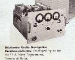 |
This is just some of the equipment produced by
P & B Inc around 1957. (Brochure provided by Herbert Rideout) |
 |
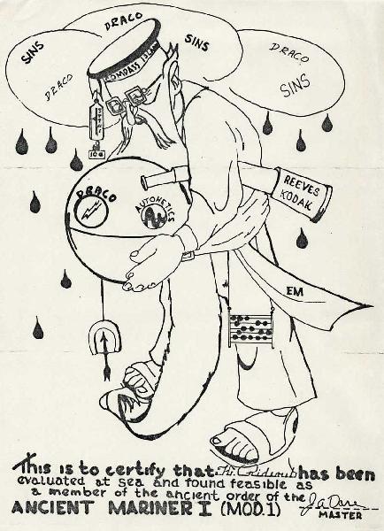
This is the certificate presented to personnel
who participated in the Draco and SINS evaluations aboard the USS Compass
Island. (Provided by Herbert Rideout)
SINS was the "Ships Inertial Navigation System" made by Autonetics a
division of North American Aviation in California. SINS was used
on the
submarines and other programs such as the Minuteman Intercontinental
Ballistic Missile and North American's Cruise Missile (GAM-77 [AGM-28]
HOUND DOG) that was launched from a B-52.
|
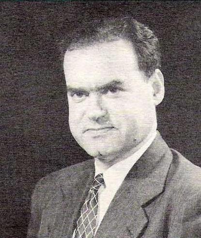
 Harold
S. Burns - Co-Founder and President P & B Inc Harold
S. Burns - Co-Founder and President P & B Inc
Harold Burns, W1KVX, received engineering training at the Eastern Radio
Institute and the University of Hampshire and is a member of the Institute
of Radio Engineers, Institute of Navigation and the American Management
Association. He has a broad background of experience in the installation,
testing and operation of Navy shipboard radio and electronic equipment
and high power international short-wave transmitting installations. During
WWII, he was chief engineer and production manager directing
projects of both applied research and the production of precision quartz
frequency elements, frequency measuring apparatus and radar components.
(Photo
and copy courtesy P & B Inc)
Harold left P&B in 1962 to start a new company Electro Marine Corp.
on Cape Cod, MA. He died 8 Sept.1999 at the Cape Heritage Nursing
Home in Sandwich, Mass., after a brief period of hospitalization. He was
81. |
 Dr.
Richard H. Woodward - Vice President Engineering, Chief Navigation
Section of P& B Inc. Dr.
Richard H. Woodward - Vice President Engineering, Chief Navigation
Section of P& B Inc.
Dr. Woodward, B.S., M.S., D.Sc. in Electrical Communications from Harvard
University, is a member of the Institute of Radio Engineers, the American
Physical Society, and the American Association for the Advancement of Science.
He helped to develop the Loran system of navigation and was of the technical
advisors assigned to the Telecommunications Research Establishment
in England. There he helped to introduce Loran into the Royal Air Force
and had close contact with the anti-jamming problems associated with
Gee and Loran. His work at Pickard & Burns included studies of radio
propagation and navigation systems for the Air Force, development
of a high precision short range navigation system for the US Navy, and
consulting on a long range navigation system at the Navy Electronics
Laboratory in San Diego along with the design and construction of equipment
for this system. (Photo and copy courtesy P & B Inc) |
VLF TRANSMISSIONS
Herbert (Art) Rideout explains the use of the AN/URH21 receiver-recorder.
"Monitoring stations were established to determine the VLF signal strengths
in the Pacific area. This was necessary to determine the feasibly
of communicating with submarines and if the signal strength was adequate
for underwater navigation. I set up stations at Shemya Alaska, Hawaii,
Fiji, New Zealand, Australia, Jakarta, Philippines, Japan and Wake Island.
At Shemya they had a BC-610 and 75A4 with a Rhombic antenna pointing at
the States. At the time I was W1KQG and I tried to make contact with
Harold Burns W1KVX but no luck, heterodynes from all the stations calling
me made it impossible. The next year, 1959 I came west to work for
North American Aviation. I hated to leave Pickard & Burns I had
many good friends and the projects were fascinating. Jack Pierce
wanted me to work for him at Harvard but the money was not there",
Knowing VLF signal strengths would no doubt help in the development
of the Omega radionavigation system.
 |
| AN/URH-21(XN-1) receiver. It was used with an
with an Esterline-Angus chart recorder. (Photo courtesy Nick England) |
SIGNAL CHARACTERISTICS
Omega utilized CW (continuous wave) phase comparison of signal transmission
from pairs of stations. The stations transmitted time-shared signals on
four frequencies, in the following order: 10.2 kHz, 11.33 kHz, 13.6 kHz,
and 11.05 kHz. During its life cycle, the system used quite a lot of
frequencies at different times. For instance, 12.1, 12.0, 11.55, 13.1,
12.3, 12.9, 13.0 and 12.8 kHz were employed. 11.05 kHz was introduced in
an attempt to enlarge the area of non-ambiguity. The difference frequency
between this and 11.33333 kHz produces a lane width of no less than 328
miles. In addition to these common frequencies, each station transmitted
a unique frequency to aid station identification.
The inherent accuracy of the OMEGA system was limited by the accuracy
of the propagation corrections that were applied to the individual receiver
readings. These corrections were in the form of predictions from tables
which were applied to manual receivers or stored in memory and applied
automatically in computerized receivers. The system was designed to provide
a predictable accuracy of 2 to 4 nm which depended on location, station
pairs used, time of day, and validity of the propagation corrections.
| TRANSMISSION INTERVAL > |
0.9 |
1.0 |
1.1 |
1.2 |
1.1 |
0.9 |
1.2 |
1.0 |
0.9 |
|
|
|
|
|
|
|
|
|
|
| A. Norway |
10.2 |
13.6 |
11.33 |
f 1
|
------ |
------ |
------ |
------ |
------ |
| B. Liberia |
f 2
|
10.2 |
13.6 |
11.33 |
f 2
|
------ |
------ |
------ |
------ |
| C. Haiku, Hawaii |
------ |
f 3
|
10.2 |
13.6 |
11.33 |
f 3
|
------ |
------ |
------ |
| D. LaMoure, ND. U.S.A. |
------ |
------ |
f 4
|
10.2 |
13.6 |
11.33 |
f 4
|
------ |
------ |
| E. Reunion Island |
------ |
------ |
------ |
f 5
|
10.2 |
13.6 |
11.33 |
f 5
|
------ |
| F. Argentina |
------ |
------ |
------ |
------ |
f 6
|
10.2 |
13.6 |
11.33 |
f 6
|
| G. Australia (Trinidad was a temporary site) |
11.33 |
------ |
------ |
------ |
------ |
f 7
|
10.2 |
13.6 |
11.33 |
| H. Japan |
13.66 |
11.33 |
------ |
------ |
------ |
------ |
f 8
|
10.2 |
13.6 |
| The Omega signals consisted of a sequence of C.W. pulses
transmitted from each station on three frequencies, 10.2 kHz, 11.33 kHz
and 13.6 kHz. The sequence was non-ambiguous and synchronized to universal
time. Each interval was separated by 0.2 seconds. The eight stations provided
world wide coverage on approximately a 10 second period. Three Omega transmissions
were needed to determine a position fix. Later, 11.03 kHz was introduced
to enlarge the area of non-ambiguity. (Table courtesy of Decca
Navigator News, June 1973) |
All OMEGA signal patterns are transmitted starting at zero
time (OMEGA Time) and are maintained at the exact starting time through
atomic clocks at each transmitting site. All frequencies are phase locked
to zero time. All frequencies cross zero phase with a positive slope at
exactly 0000 OMEGA Time.
Initially OMEGA station transmissions were started at universal time.
However, universal time is corrected for changes in the earth's rate of
rotation; these conditions, called leap seconds, are made periodically.
Corrections to OMEGA Time to account for leap seconds are difficult because
of complex interrelationships between stations. Additionally, signals used
during the time change present a synchronization problem. Consequently,
OMEGA Time is maintained at a steady rate and is not updated. All OMEGA
stations are timed and controlled by a cesium beam atomic clock which is
accurate to 1 second in 3000 years. The overall accuracy is on the order
of a few parts in 10^12.
STATION TABLE
STATION
LETTER |
STATION LOCATION
|
ANTENNA TYPE
|
LAT/LONG
|
TRANSMISSION STATUS
|
|
|
|
|
|
| A |
Bratland, Norway |
Valley span |
66° 25'N
13° 08'E |
Normal 10 kw transmission. |
| B |
Paynesville, Liberia |
Grounded tower |
06° 18'N
10° 40'W |
10 kw transmission .
Modal interference at night. |
| C |
Kaneoke, Hawaii |
Valley span |
21° 24'N
157° 50'W |
Normal 10 kw transmission. |
| D |
LaMoure, ND |
Insulated tower |
46° 21'N
98° 20'W |
Normal 10 kw transmission. |
| E |
Plaine Chabrier,
LaReunion (Indian Ocean) |
Grounded tower |
20° 58'S
55° 17'E |
Normal 10 kw transmission. |
| F |
Golfo Nuevo, Chalut
Argentina |
Insulated tower |
43° 03'S
65° 11'W |
Normal 10 kw transmission. |
| G |
Woodside, Victoria, Australia. Temporarily
assumed by Trindad |
In planning |
38° 29'S
146° 56'E |
Came on line around 1980.
Trinidad power level was 1 kw |
| H |
Shushi-Wan,
Tsushima Island, Japan |
Insulated tower |
34° 37'N
129° 27'E |
Normal 10 kw transmission. |
| Omega summary information was broadast
from WWV, Boulder Colorado at 16 minutes after each hour in a 40 second
duration. |
The VLF range of 10-14 KHz was selected as the best range for
OMEGA primarily because of:
1. Presence of a wave guided mode to VLF signals which follows the earth's
curvature and provides signal detection over great distances with a relatively
low (10KW) power output.
2. Excellent stability of VLF signals.
3. Relatively wide distances between points where phase measurements
would be the same (distances between points of equal phase measurements).
VLF WAVE GUIDED MODE
VLF propagation contains several different transmission modes: ground
wave. sky waves and wave guided wave.
The wave guide effect occurs when a wave passes through a cavity which
reflects the wave and confines it to the enclosed space within the cavity.
An effect similar to the wave guide effect occurs when very low frequency
transmissions travel over the earth's surface. Signals in the 10-14 KHz
range behave as though propagated through a waveguide of concentric spheres.
In this case, the spheres are the earth and the ionosphere.
The stability of an OMEGA signal is the primary reason these waves are
desirable for navigation. Stability of a VLF OMEGA signal indicates the
wave propagates with similar characteristics, without distortion. at almost
any
distance from the transmitting station as long as it is receivable. This
stability is confirmed through monitoring of OMEGA VLF signals at various
earth locations. Monitoring has also shown changes in exact phase measurement
of VLF signals. Actual measurement at a given time can be predicted with
great accuracy even though exact phase measurements differ greatly day
to night. season to season.
Wave guided signals travel great distances from the station with almost
unlimited range over water; over land they attenuate at a greater rate.
The greatest loss of signal occurs over the ice cap. A wave propagated
in one direction over water (the long way around the world) could be received
while a direct signal from the station might not be received due to signal
attenuation over an ice cap. When this occurs the predicted position fix
accuracy becomes extremely low and the signals should be considered invalid.
Also, when the receiver is a great distance from the transmitters, signals
may be received from both directions, resulting in a combined signal phase
shifted an unknown amount. Therefore, use of OMEGA signals is not recommended
when the receiver is more than 8000 NM (great circle distance) from
the transmitting stations.
SYSTEM ERRORS
The earth is not a perfect waveguide. The imperfect walls of the earth
ionosphere waveguide affect signals in many ways. Phase velocities in the
VLF range are primarily dependent upon the condition of this waveguide
through which they are propagated. The earth's waveguide condition is a
function of the shape and height of the ionosphere which is in turn a function
of the position of the sun and the season of the year. As a consequence
of these, and other factors, there are eight (8) basic error sources which
contribute in varying degrees to the overall OMEGA system accuracy. Two
out of 8 error sources are described below. The other six were missing
in the source material.
DIURNAL EFFECT
The first error source of concern is called the diurnal effect. It is
principally associated with the sun's position since its radiation adjusts
the height and shape of the ionosphere. During daylight hours, the ionization
layer will lower to about 70 KM, thereby increasing the phase velocity.
At night, the layer moves up to about 90 KM, thus decreasing the phase
velocity. This effect will also be seasonal and, of course, nonlinear during
transition.
A long propagation path may be either entirely sunlit (day), entirely
dark (night), or experiencing mixed illumination (transition). For long
paths, night may be only a few hours; for Arctic paths during the summer
months there may be no night at all. Propagation tends to be most stable
during the day although conditions do vary slowly. At night conditions
tend to be constant but less stable than during the day. Transition periods
are of intermediate stability and present additional complications in prediction
and application.
GROUND CONDUCTIVITY
The second source of error is ground conductivity. Extreme variations
in phase velocities are detectable between sea water, representing
low attenuation, and ice which is high in attenuation and hence slows the
phase velocities. Water is a near perfect conductor in the VLF spectrum
and does not greatly affect the signal.
Propagation correction tables and formulas were based on theoretical
models calibrated from worldwide monitor data taken over long periods.
A number of permanent monitors were maintained to assess the system accuracy
on a long term basis. The specific accuracy attained depended on the type
of equipment used as well as the time of day and the location of the user.
In most cases, the accuracies attained were consistent with the 2 to 4
nm stated in the system design goal. There were a few cases where much
better accuracy was reported. A validation program conducted by the USCG
indicated that the OMEGA system met its design goal.
OMEGA had an availability of greater than 99 percent per year for each
station and 95 percent for three stations. The annual system availability
was greater than 97 percent which included scheduled off air time. Scheduled
off air periods were announced up to 30 days before the off air activity
was to occur.
The system provided independent position fixes once every ten seconds
and was capable of two or more lines of position (LOP's) fix . Due to the
fact that Omega antennas were towers around 1,200 feet tall, that
made the system very expensive to install.
AMBIGUITY
In this CW system, ambiguous LOP's occur since there is no means to
identify particular points of constant phase difference which reoccur throughout
the coverage area. The area between lines of zero phase difference were
called lanes. Single frequency receivers use the 10.2 kHz signals whose
lane width is about eight nautical miles on the baseline between stations.
Multiple frequency receivers extended the lane width, for the purpose
of resolving lane ambiguity. Lane widths of approximately 288 nm along
the baseline could be generated with a four-frequency receiver. Because
of the lane ambiguity, a receiver had to be preset to a known location
at the start of a voyage. The accuracy of that position had be known with
sufficient accuracy to be within the lane that the receiver was capable
of generating (i.e., 4 nm for a single frequency receiver or approximately
144 nm for a four-frequency receiver).
Once set to a known location, the Omega receiver counted the number
of lanes it crossed in the course of a voyage. This lane count was subject
to errors which could be introduced by an interruption of power to
the receiver, changes in propagation conditions near local sunset and sunrise,
and other factors. To use the single frequency Omega receiver effectively
for navigation, it was essential that a dead reckoning plot or similar
means be carefully maintained and the Omega positions compared to it periodically
so that any lane ambiguities could be detected and corrected.
The accuracy of an Omega phase difference measurement was independent
of the elapsed time or distance since the last update. Unless the Omega
position was verified occasionally by comparison to a fix obtained with
another navigation system or by periodic comparison to a carefully maintained
plot, the chance of an error in the Omega lane count increased with time
and distance. These errors were reduced in multiple frequency receivers
since they were capable of developing larger lane widths to resolve ambiguity
problems.
Omega receivers were used in the Number 3 position on some 747s as
backup for the two Inertial Navigation Systems.
AN/SRN-12
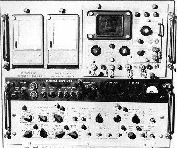 |
| The AN/SRN-12 is one example of an OMEGA receiving set.
It's a solid state, single frequency, phase-locked, superheterodyne navigation
receiver designed for use in surface ships. The AN/SRN-12 received the
10.2 kHz transmissions, phase-locks and tracks any four selected stations'
signals, measured the phase of each tracked signal with respect to a highly
stable internal oscillator and computed and displayed three selected phase
differences (LOPs). Lines of position were displayed on nixie tube indicators
and a permanent record was stored on a graphic recorder. A built in oscilloscope
was used for visual monitoring of received OMEGA signals and troubleshooting.
An built-in emergency battery power supply maintained synchronization during
brief (up to 5 min) power outages. (Photo courtesy RCN) |
 |
| This is an example of a processor receiver unit removed from
an unknown commercial aircraft. It has a serviceable tag from Avionics
& Aircraft Systems, Inc. dated 1/30/92. The nameplate reads: CANADIAN
MARCONI COMPANY CMA-771, RECEIVER PROCESSOR UNIT, OMEGA NAVIGATION SYSTEM,
PN 473-157-023. |
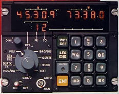 |
| Canadian Marconi CMA740 control head. (e-Bay photo) |
CLOSURE
With the Global Positioning System (GPS) being declared fully operational,
the use of OMEGA had dwindled to a point where continued operation was
not economically justified. The 1994 edition of the United States Federal
Radionavigation Plan (FRP), which delineates policies and plans for federally
provided radionavigation services, stated "the U.S. expects to continue
OMEGA operations until September 30, 1997, to accommodate the transition
of civil aviation users to GPS. Continued operation after that date
will depend upon validating requirements for OMEGA that cannot be met by
GPS or another system." The Federal Aviation Administration (FAA) completed
its review of Omega navigation requirements for the U.S. aviation industry
and notified the U.S. Coast Guard that most users will complete their conversion
to GPS technology by September 1997. OMEGA was shut down precisely at 0300Z
on September 30, 1997 - the end of another era. To VLF experimenters, the
very high power OMEGA signals were both a blessing and a curse; a blessing
in that they provided convenient test signals in the 9.5 to 14 kHz range,
and a curse in that they tended to interfere with the reception of natural
radio phenomena such as "whistlers" and "dawn chorus".
Besides affecting users, the closure of Omega had a small impact on
tourism. Because of their prominent antennas and interesting mission, many
Omega stations were recognized in their local areas as major tourist attractions,
including official listings and pictures in area tourist brochures. Omega
station North Dakota was located in the town of LaMoure, with a population
of less than 1,000. In this small town is located the Omega Motel, the
Omega Plaza, and the Omega Room at one of the restaurants. After Omega
ceased, the USN took over the site from the US Coast Guard and continued
VLF communications under the name of Naval Computer and Telecommunications
Area Master Station Atlantic (NCTAMSLANT). The mission statement of the
new station is: " To manage, operate, and maintain those facilities, systems,
equipment, and devices necessary to provide requisite communications
and information system support for the command, operational control and
administration of the naval establishment, and the fixed submarine broadcast
system; to test and evaluate new Very Low Frequency (VLF) broadcast technology
and minimize downtime of operational sites during VLF system upgrades and
major transmitter and antenna maintenance". The people of LaMoure
will not soon forget the Omega system as the 1200 foot tower still
looms in the western horizon and a number of retired Coast Guardsmen now
reside in LaMoure.
Omega Station Norway had a prominent sign along the road near the helix
building proclaiming their antenna as the longest antenna span in Europe.
The Japan tower was the highest structure in Japan, and the Argentina and
Liberia towers were the tallest structures in their entire continents.
Australia registered over 10,000 visitors per year to its station.
THE MESSAGE WHICH ANNOUNCED THE CLOSURE OF THE SYSTEM
The following message was sent by the United States Coast Guard
to all OMEGA users advising of the system shutdown.
P 011416Z OCT 97
FM COGARD NAVCEN ALEXANDRIA VA//NIS//
SUBJ: OMEGA STATUS AS OF 01 OCT 97
1. THE OMEGA NAVIGATION SYSTEM TERMINATED AND ALL STATIONS CEASED OMEGA
TRANSMISSIONS AT 0300Z 30 SEPTEMBER 1997 IN ACCORDANCE WITH NAVCEN OPERATIONS
ORDER DATED 141026Z AUG 97.
2. OFF AIR PERIODS 221000Z SEP 97 THROUGH 300300Z SEP 97:
A. NONE
B. NONE
C. NONE
D. NONE
E. NONE
F NONE
G. NONE
H. NONE
3. REDUCED POWER PERIODS 221000Z SEP 97 THROUGH 300300Z SEP 97:
A. NONE
B. DOWN 3.7 DB 221000Z TO 300300Z
C. NONE
D. NONE
E. DOWN 1.7 DB 221000Z TO 230250Z
DOWN 1.3 DB 230715Z TO 231215Z
DOWN 4.2 DB 231415Z TO 232355Z
DOWN 1.7 DB 241000Z TO 242225Z
DOWN 1.4 DB 251440Z TO 251951Z
DOWN 1.2 DB 260101Z TO 260230Z
DOWN 5.0 DB 260740Z TO 270608Z
DOWN 2.5 DB 271602Z TO 280335Z
F. DOWN 1.9 DB 221700Z TO 230731Z
DOWN 1.2 DB 241839Z TO 242023Z
DOWN 2.4 DB 272100Z TO 280358Z
G NONE
H DOWN 1.6 DB 231230Z TO 231810Z
DOWN 1.6 DB 250305Z TO 251800Z
DOWN 1.6 DB 261750Z TO 262220Z
4. QUESTIONS REGARDING OMEGA STATUS/OPERATION MAY BE DIRECTED
TO: PHONE NUMBER (703)313-5900.
A facsimile transmission received by the Navigation Center (NAVCEN)
from the Japanese Maritime Safety Agency truly summarized the 25 year relationship
between the U.S. and Japan. The FAX, received just days before the signal
was terminated stated:
..."(The final status message) will shine brilliantly, foot marking
the world wide radio navigation history cooperatively linking OMEGA with
six partner nations. We can't say enough in praise of your excellent duties.
In Japan, both the Station and the Analysis Office employees amount to
nearly three hundred persons since opening time. They have a favorable
impression of the system. Your friendship and kind support with us over
the years has been deeply appreciated. It will stay with me as a rewarding
memory of the valuable experience received from OMEGA. I hope that the
OMEGA community members will continue to have a successful and enjoyable
life."
These kind words were expressed by Toshiichiro Kawamura, Director of
JMSA.
AN OMEGA POEM
This Omega Poem was published in the USCG Radionavigation
Bulletin Fall/Winter 1997, after the system closed.
Omega ... Omega in the sky.
Ships and planes use you as their eyes.
You've run so long, Your waves held high.
You cover the world in the blink of an eye.
You sing a song like no other.
Your cycle covers places that no other could cover.
Your lattice ... out-stretched like the arms of a mother,
helping so many, no matter what weather.
We bid you farewell, so long and good bye...
and from all the men, past and present,
we salute you and all who have served under your majestic tower,
here at OMSTA LaMoure, North Dakota...
And Just like your song,
We are gone ... In the Blink of an eye
Fireman Adam Powers,
OMSTA LaMoure, North Dakota
FOOTNOTES:
1. The use of an RF filter on any receiver effectively
extends the range.
REFERENCES and CREDITS:
1) The Journal Of Navigation - Chapter 4. W.F. Blanchard,
Royal Institute of
Navigation; Vol 44, No. 3; Sept 1991.
Used with permission.
2) USGC Web sites: www.uscg.mil/lantarea/bjc/aton.htm
www.navcen.uscg.mil/omega/ogeninfo/omstat.txt
3) DGNSS web page: www.dgnss.com/descriptions/omega.htm
4) USCG Radionavigation Bulletin - Spring/Summer 1996.
Omega Navigaton To Be Terminated;
Lt. Kenneth Pierro, NAVCEN,
New Timing and Control Equipment
for Omega; R.C. Hoyler, NAVCEN
USCG Radionavigation Bulletin - Fall/Winter
1997.
Omega Silent After 25 Years Int's
Service; LCDR Lori Mathieu, Lt Kyle Smith, Mr. Vinicio Vannicola.
5) Herbert Rideout e-mail: <wa6ipd(at)dslextreme.com>
6) Excerpts from "Field Intensity Measurements and Draco
Performance In the Mediterranean Sea" Aug 6, 1958. Publication 458, prepard
by Pickard & Burns , Needham, Mass.
7) Pickard & Burns information brochures 1957.
8) Stuart A Wolf e-mail: <stuart.wolf(at)nats.co.uk>
9) James Churchill <jchurchill(at)milcom-systems.com>
10) Enabling Network Centric Warefare http://www.nctamslant.navy.mil/index.php?id=392&secid=14
11) RCN's N.E. Tech TQ6B Common Equipment Manual.
12) Nick England <nick(at)navy-radio.com>
Back to Index Page
May 14/18