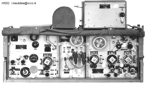
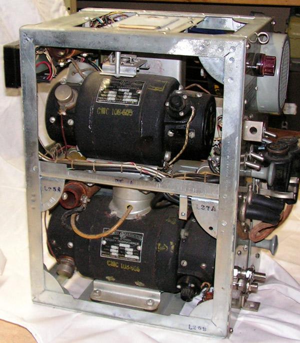
Wireless Set No.
C52
This was a mobile
transmitter/receiver developed in 1943 for general purpose use from Brigade
to Division communication. The C-52, developed from the No.
9 Set, proved to be very popular in all quarters although it was noted
that while performance on medium power was good, there was a tendency to
overheat on high power. This set was particularly valuable in airborne
roles and for command vehicle use. The U.K. alone spent over 14 million
dollars purchasing 352 sets
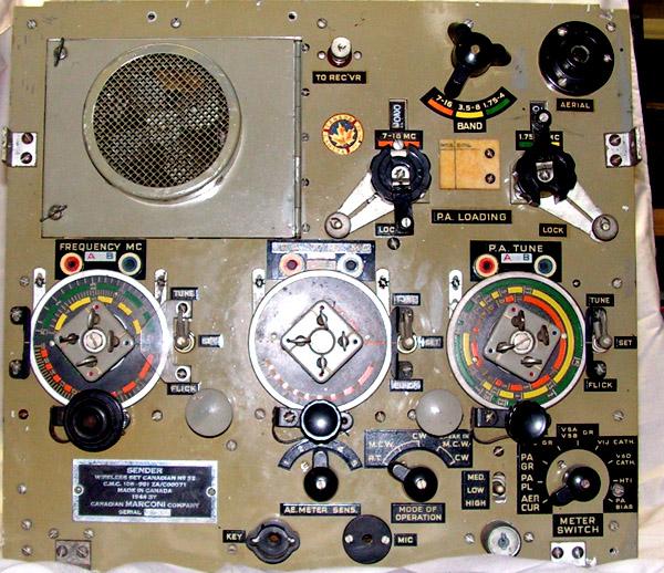
SPECIFICATIONS
Modes :R/T, MCW and
CW
Frequency Range:
1.75-16 MHz
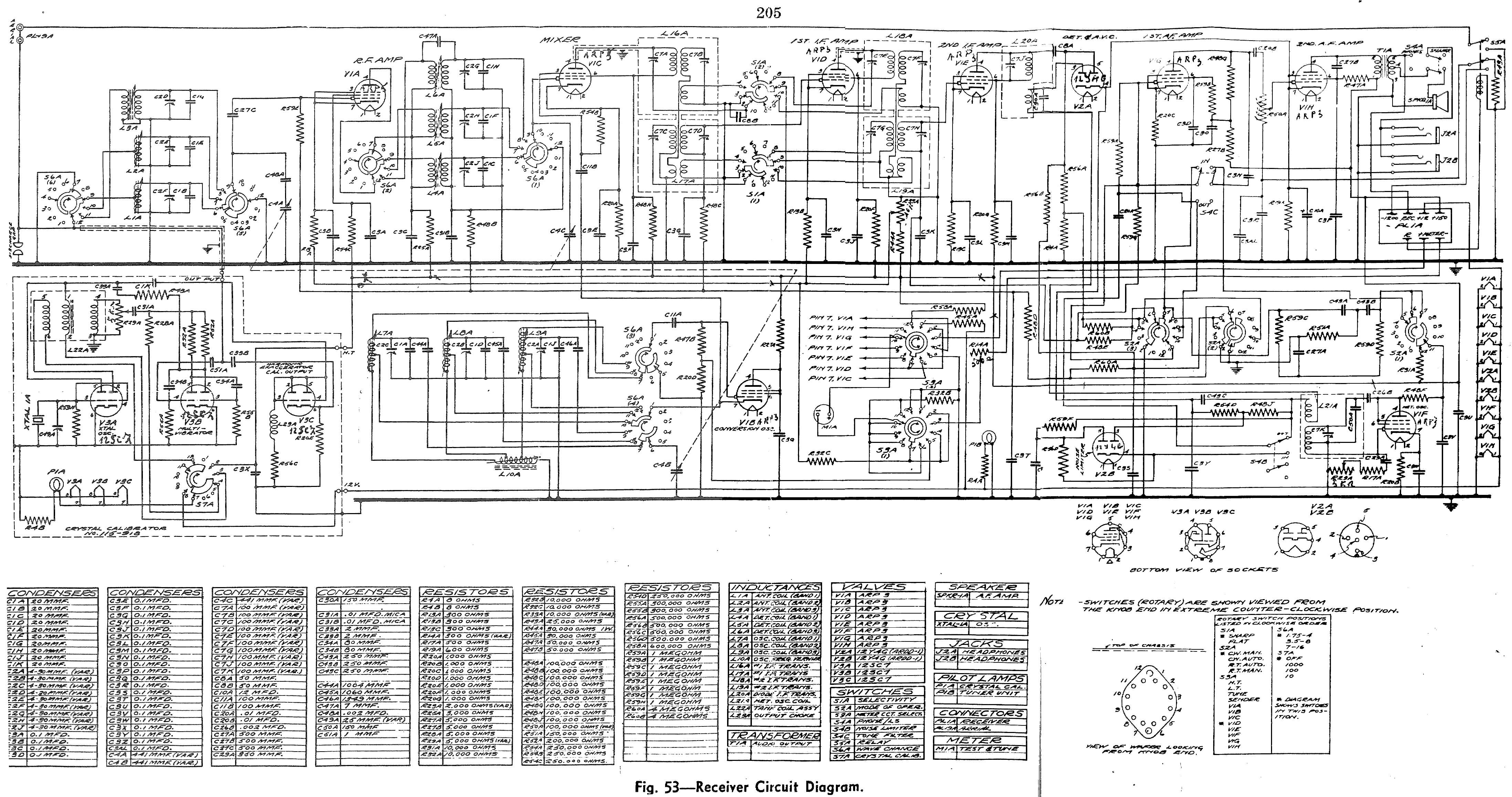
Receiver type: 108-953
ZA/C00072
Transmitter type:
?
Power Output:
Up to 100 watts. Uses a 813 tube and grid modulation.
Frequency Control:
Master oscillator
Vintage: 1944
Comment: Canadian
design which replaced the No. 9 Set. In the UK, the No 11 set was manufactured
by E.K. Cole