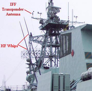
Jim Dean, ex-RCN, explains the reason why the whip antennas
are raked outboard. "The design of the Canadian Patrol Frigate (CPF) HF
communications suite included a brass model analysis of the antenna system.
This was not a simple exercise. It was done for a couple of reasons. The
decision was made that the CPF would use a multiplexed HF transmit system
that would permit future frequency hopping according to the NATO STANAGS
that had been approved around 1987. This required broadband antennas
that did not need antenna couplers In contrast, the DDH 280s class had
tuned antenna couplers for each transmitter and set for discrete frequencies.
This configuration would have been unsuitable for frequency hopping.
Because a ship is a lousy platform for LF, MF and HF antenna systems, the
brass model was used to try and optimize the HF antenna layout which would
yield input impedances at each antenna that would provide the low
broadband VSWR that would allow frequency hopping and use of the multiplexed
transmitter system. I cannot remember if intermodulation products were
a consideration of the brass model, or not. We certainly did extensive
intermod studies to see how the intermod from the HF transmit system would
affect the HF receive system.
In the brass model studies, moving one HF antenna affected the input
impedance of the others. Input impedance was also affected by the proximity
of superstructure, major deck fixtures, etc. As I understand it, the HF
whips were angled as part of the package to provide the needed input
impedance for acceptable VSWR over the frequency range for each antenna.
Besides that, there are never enough HF transmitters aboard a ship.
When HMCS Halifax was first commissioned, the CO wanted to use the centre-line
emergency whip with its transmitter to augment the multiplexed HF comm
system. Flashing up the emergency transmitter at the same time as the HF
transmit system caused some major problems as the RF from the emergency
transmitter fed into the HF whips and in effect changed the impedance
enough to knock the transmitters off line. The emergency comm system
was designed simply as a "needed to get home" backup to the HF comm
system and was never meant to be operated simultaneously. I don't know
how the system works today but I understand they have increased the HF
multiplexing from 6 to 8 transmitters and are even contemplating 10".
 |
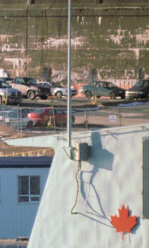
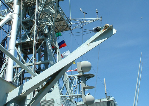
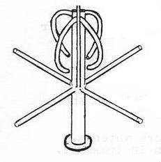
| Photo # Radio Ant 6. This is the feed arrangement for the two
canted HF whip antennas. Below the mounting plate is the antenna coupling
device. (Photo by Jerry Proc) |
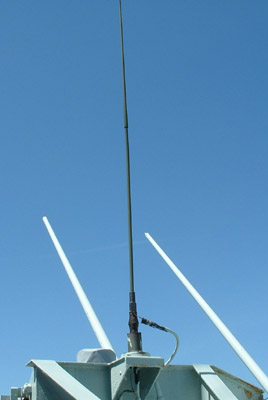 |
| Photo #Radio Ant 16. A pair of Land Forces Support Radio (LFSR)
whip antennae are mounted on the port and starboard sides, midships. (Photo
by Jerry Proc) |
 |
|
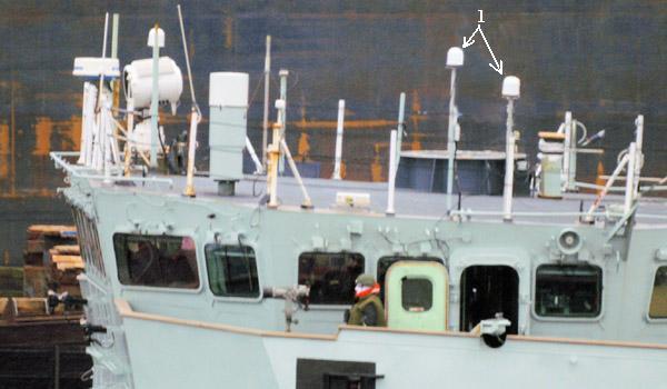
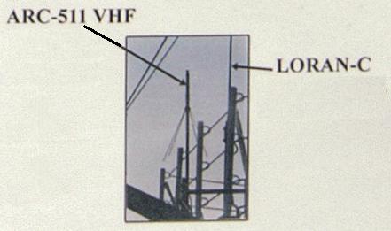
ARC-511 and Loran-C antennas atop the bridge. (Canadian Navy
image)
|
NOTES:
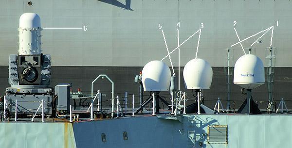
[1] On Halifax class ships, the functions called "UHF main" and "UHF
emergency" can be interchanged by the rearrangement of patch cables in
the Communications Equipment Room (CER) which is forward of the CCR and
in the Emergency Radio Room (ERR - back aft on 2 deck below the hangar).
The main UHF comm antenna was formerly designated as the one on the foremast.
In an effort to eliminate dead spots and improve communication with
the helicopter, the main UHF antenna function was moved to the aft position
near the STIR radar. The one antenna on the foremast is now the UHF emergency
antenna while the other is a spare.
[2] Per Don Brandi: Generally, AS numbers assigned to antennas are for
US and Canadian registration only. Most manufacturers have their own antenna
numbers and AS numbers. They must be similar electrically and physically
(exterior dimensions), while the interior construction can be different.
So any manufacturer could have the same AS number as long as the antenna's
share the required similarities and identical performance.

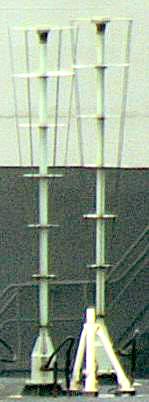
 Halifax class ships are fitted with whip antennas made by CHU Associates.
Since no photo is available, the Valcom AS-3772 (35 foot whip) and the
AS-3770 (18 foot whip) are presented here as a substitute. CHU Antennas
are metal based while Valcom antennas are fibreglass based. They
still share the same AS number [2] and are made to the same MIL-SPEC, MIL-A-29517(EC).
Halifax class ships are fitted with whip antennas made by CHU Associates.
Since no photo is available, the Valcom AS-3772 (35 foot whip) and the
AS-3770 (18 foot whip) are presented here as a substitute. CHU Antennas
are metal based while Valcom antennas are fibreglass based. They
still share the same AS number [2] and are made to the same MIL-SPEC, MIL-A-29517(EC).
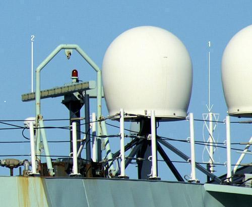
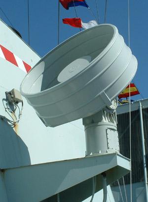
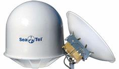 Photo
# Radio Ant 10. The WaveCall 6006 is a marine VSAT antenna, 1.5-meters
in diameter and operates in the Ku-Band. This antenna is suitable for file
and image transfer, video conferencing, e-mail, Virtual Private Networks
(VPNs), and database backup.
(Image and all copy courtesy Sea Tel)
Photo
# Radio Ant 10. The WaveCall 6006 is a marine VSAT antenna, 1.5-meters
in diameter and operates in the Ku-Band. This antenna is suitable for file
and image transfer, video conferencing, e-mail, Virtual Private Networks
(VPNs), and database backup.
(Image and all copy courtesy Sea Tel)