Allied Analysis of Electronic Transmissions in WWII
by Jerry Proc VE3FAB
(Author's Original Copy)
This story was edited and published in the Antique Wireless
Association "Review" publication #36 2023
During WWII, the most common method of locating enemy radio transmissions
was through the use of radio direction finding, whereby two or more monitoring
stations would obtain bearings on enemy transmitters and then triangulate
the results to obtain a fix. There were at least two other techniques that
could provide data or intelligence about the characteristics of the transmitter
making the transmission and the Morse code sending-style of the operator.
These techniques were known as Radio Finger Printing (RFP) and a code-named
process called TINA, which were used by the Allies. When used jointly,
TINA and RFP were known as Z intelligence or Z service in the Commonwealth
countries. TINA was derived from the last four letters of the word Serpentina,
a name used for the method of recording hand-sent Morse transmissions on
paper tape for later analysis. As with many other WWII activities, RFP
and TINA were shrouded in a cloak of secrecy. Finally, the methods and
results of noise investigation are described.
RFP
Radio Finger Printing (RFP) was the process used to catalogue a specific
transmitter through its distinct characteristics with the aim of locating
it at a future date. The idea was to identify individual transmitters
by their emitted waveform. The rectified signals were applied to a cathode
ray tube, (without a time base), and photographed onto moving film.
The German naval transmitters were remarkably uniform and showed little
more than an initial damped oscillation produced, perhaps, by a carbon-pile
voltage regulator. The Italian mobile naval transmitters were remarkably
erratic, and never looked the same twice; while their shore stations could
often be identified by the ripple frequency of anything but 50 Hz.
 |
| This is an example of a radioteletype signal whose transmitter
is slightly faulty. The keying envelope is perfectly formed except for
the 100 Hz ripple riding on the signal. To see more transmitter faults
detected via the RFP equipment, please
select this link, (Courtesy Collingwood Heritage collection) |
RFP was very useful technique in checking Allied transmitters
when used for deception purposes to ensure that they really did correspond
to the transmitters that they were Here is just one example extracted from
page 172 of the book Secret Warfare by David Kahn.
"Portable transmitters were meant to emit maximum power with
minimum size and more often than not, they were not provided with the necessary
number of circuits for obtaining a perfect tone quality. Specifically,
the British B2 and BP3 sets were stabilized with quartz crystals, but their
characteristic tones could not fool the Germans about their identities.
A number of these were set up on British soil and operated as phantom networks.
The German interception services located this phantom network and localized
it. Once they realized that the transmissions were coming from Britain,
they abandoned their scrutiny of this network. At this point, Special Operations
Executive (SOE ) took the radios out of this phantom network as needed
and dropped them by parachute into occupied territory. These sets were
then added to the real clandestine network. By doing this, the German radio
location services were slowly but surely led into saturation and chaos".
It also needs to be emphasized that radio fingerprinting was never meant
to be used standalone, but rather, to be used in conjunction with other
identification tools such as TINA.
TINA in the UK
TINA was the method used to recognize specific radio operators by their
Morse code "fist" and habits. One definition has the code name of
TINA as being derived from the Latin word "tinea" which meant "worm".
TINA was the process that involved studying the distinctive characteristics
of particular Morse code operators to identify and tracing the locations
of those operators, for which might show that a particular operator
has changed ships which may indicate damage or destruction to the previous
ship or even a re-assignment. Each operator had a distinctive touch, or
'fist'. Some were slower while others were jerky; some held down the key
or paused between dots and dashes for different lengths of
time and so on.
Extracts from a TINA article written by John Roscoe G4QK provide a more
detailed picture of TINA.
"The early TINA recordings of Morse were made with a siphon-pen recording
on paper tape using a device known as an
undulator.
At a later date, Morse transmissions were recorded on 35 mm film with a
slow running RFP machine. This allowed measurements to be made through
considerable noise conditions (QRN). This permitted the desired waveform
to be distinguishable from the ambient noise.
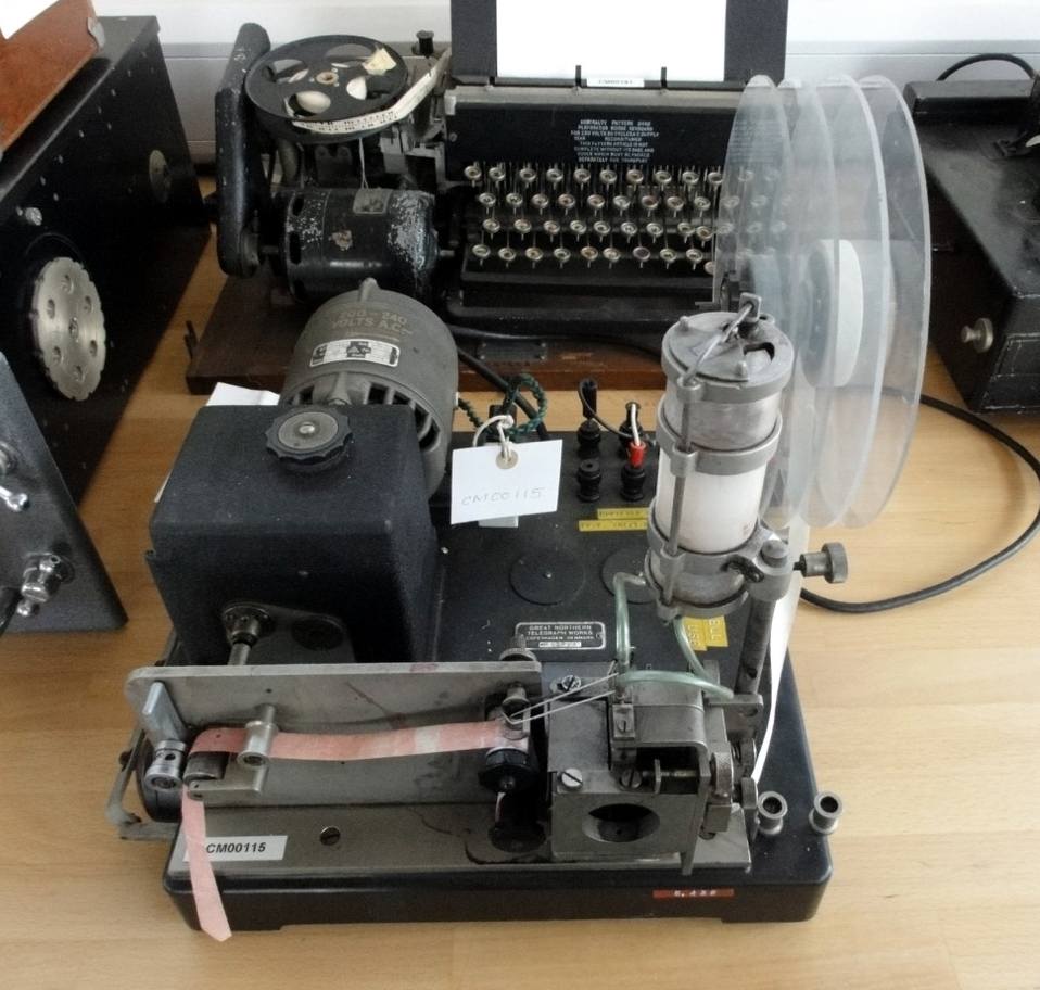 |
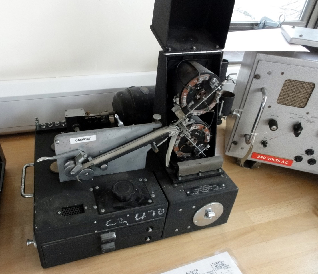
| Above and below: Two undulator
variants. The upper device is the UG-6 while the lower device is type UG-8
The UG-8 has its dust cover raised to expose the mechanics. (Photos
courtesy of the Collingwood Heritage Collection) |
 |
 |
| A bridge unit, similar to this one, connected
the receiver audio output to the input of the undulator. By arranging one
or more valves to alter the balance of a resistance bridge network across
which is connected the recorder, equal mark and space currents can be passed
in opposite directions through a single coil. The device , in all of its
forms became known as a "bridge." Click on image to enlarge. (Photo
by Clive Kidd) . |
In the UK, the standard method of measuring Morse involved
several WRENS. (Women's Royal Naval Service ; WRNS; popularly and officially
known as the WRENS) Two WRENS at a time would start the process. One would
read off the measurements from the film using an enlarger and the other
transferred them to graph paper. The dashes and dots were then marked with
red and blue circles. Attempts at identification with previously captured
records were made by direct comparison. This procedure inevitably
relied on the acuteness of observation and perhaps the memory of
the operator on duty. This was not a fast method so two ideas were pursued
to help automate the process.
(1) A method of recording that would permit simple and more rapid measurement.
(2) A machine-compatible system for classifying the records.
To summarize:
On the issue of measurement, the TINA device would make a vertical deflection
on the 35 mm film instead of a horizontal one. The vertical
deflection would correspond to each dot or dash in the Morse character.
The idea behind the mechanical classification scheme was to extract
parameters from the Morse that could be coded numerically and searched
mechanically. In those precomputer days, the best machine that was
available was the Hollerith 80-column punched card sorter with a built-in
8-column group selector which worked at the astonishing rate of 400 cards
per minute! However, there were issues with the generation of Morse
code before a solution could be implemented.
In the WWII era, Morse was sent mostly by straight key. Semi automatic
keys did exist in 1942 but they sent relatively clean code so it would
be challenging to make an identification to a specific operator using
TINA. So TINA was limited to the analysis of Morse generated by straight
keys. In addition, sidetone oscillators were uncommon, so practically
all the operators wouId have been sending by "feel" alone.
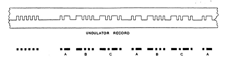 |
| At the top is the output tape of the undulator
with the equivalent Morse characters shown below. This is how TINA started
but later on the system used photographic film, From this hard copy, the
TINA operator could study the length of the dots and dashes in the character
stream. (Courtesy of High Speed Recording of Radiotelegraph Signals) |
The most consistent characteristic in Morse code was the ratio
between an adjacent dot and dash in the longer symbols. For example, the
dash might be markedly longer than the following dot in D, B, and 6. This
would almost certainly be matched by a similar disparity in U, V, and 4.
Invariably, A and N did not fit into this pattern. The fate of the other
dots, in 4 and 6 for example, 'was a matter of individual taste. This simplified
measurements, as there was no need to establish a notional average length
for the dot. The ratio between adjacent elements could be immediately coded
on a scale of 1 to 10, with adequate provision for the spread of results.
The most interesting application of this technique was to the U-boats
in the North Atlantic. Although they carried more than one radio operator,
only one appeared to do the transmitting, thus reducing the number of our
records that had to be maintained by TINA personnel. Mass training
for the German U-boat radio operators was so standardized that their
style of sending made TINA analysis impractical.
The U-boats were at sea, generally, for a maximum of 6 weeks, so a preliminary
scrutiny could be made, and had to be made, in a few minutes of all
records obtained within this period. More leisurely checks could then be
made for long term files. Of course this was only part of the picture,
as direction-finding, RFP, decoding. etc., would also have contributed
their intelligence to the records base. Of course, the "victims"
were well aware that they were being monitored but since the U-boats invariably
sent short messages (quite unlike the Italian submarines in the South Atlantic).
they presumably felt the risk was small ".
To ensure the authenticity of messages sent from behind enemy lines,
each agent was subjected to a TINA analysis of his fist prior to being
dispatched to the field. This consisted of sending all the letters
of the alphabet and all the numbers 0 through 9.. This was recorded on
paper tape that moved at 16 feet per minute. At that speed, each dot was
1/4 inch long. on the paper tape. The irregularities of dots, dashes and
spaces characteristic of the individual's operating style could easily
be compared with the paper tape record on file.
TINA and RFP in New Zealand
In the early 1940s, at least seven New Zealand signals intelligence
stations were constructed and operated as part of the British-American
intelligence system. Three of these stations were set up in Awarua
(ZLB) , Auckland (ZLF) and Waipapakauri (WPP) which became
part of the US Navy's Pacific-wide DF net. The purpose of the
net was to locate Japanese ships and other sources of enemy radio transmissions.
In 1942, a new station (RNW) joined the net. RNW, was the Post
Office call-sign for Renwicktown, near Blenheim NZ. In the direction finding
stations, little was told about RNW's function except that it was
a naval W/T station and that all personnel were to fully co-operate with
it. The new station would be staffed by the Womens Royal New Zealand Naval
Service (WRENS). These WRENS were all competent operators, and fluent
in the Japanese Katakana code. Many years after the war, it was revealed
that RNW was set up as a Radio Finger Printing station.
The job of the New Zealand D/F net, was to take radio bearings on enemy
signals that were radioed from the US Pacific Fleets Headquarters (NIT)
in Hawaii, and later Guam. RNW tracked around with these frequencies and
call-signs received from NIT.
At RNW, the identification process was started by photographing signals
which were displayed on an oscilloscope and examining the developed print
in minute detail for any peculiarities in the received waveform. These
would then be compared with previously recorded photographic strips to
see if there were any similarities which would enable the identity of the
station or vessel to be made.
The RNW station itself was a two-storey farmhouse taken over for the
duration of the war by the New Zealand Ministry of Defence. It was
at the end of a long no-exit road at Rapaura, terminating on the banks
of the Wairau River.
The house was altered to allow an operations room downstairs but the
radio equipment and sleeping quarters for the eight Wrens who would be
staffing the station were on the second floor. The area surrounding the
house was enclosed with a six-foot high, barbed wire fence, with a locked
gate, and security was provided by a detachment from the Guards-Vital Points
which camped on the site.
It was an ideal radio receiving situation, away from all interference.
There was a clump of tall poplar trees close to the house and these were
used to provide masts for the inconspicuous aerial, which was erected by
using a bow and arrow! The equipment was based around a special receiver
incorporating an oscilloscope and movie camera, known as REB 2,
which had been sent out by the British Admiralty from London. Also
provided were two Collier and Beale HRO type receivers, fitted with oscilloscopes.
This equipment was installed by an ex-Post Office telegraphist who was
a Leading Telegraphist in the RNZVR. He remained at the station to instruct
the staff in the Japanese Katakana code and left when they were proficient.
The operating procedure was to tune into the frequency and identify
the callsign which had been signalled from Awarua on the landline. The
signals were checked on the oscilloscope attached to the standard receiver
for photographic suitability. If suitable, a button was pressed which brought
into operation the REB 2 equipment which then started photographing the
waveform on the oscilloscope.
Later, when the film was developed, the Classifier examined the films
in detail looking for imperfections such as harmonics, damped waves, key-relay
effects and anything else peculiar to that transmitter. In many cases the
operators style of sending could be recognized and this would be a further
clue to the stations identity.
The photographic strip details were recorded, given a file classification
and stored for future reference. Once a file had been built up the station
could be identified by the signal it emitted and the style of sending.
This meant that no matter how often the callsigns were changed and the
Japanese changed theirs daily for a while the station or vessel could
be identified irrespective of call-sign.
The operators worked during the night, 6 pm to 6 am, on four-hour watches,
and the classifiers during the day, examining the photographic strips that
had been received overnight. If there was incoming traffic of importance
during the night or if it was busy, the operators would thump on the ceiling
with a broom handle to wake up the sleeping classifiers to bring them down
to attend to the urgent traffic and clear the filled cassettes. The results
of the classifiers analysis would be suitably coded up and telephoned
to the Navy Office in Wellington over a Scrambler (inverted speech) telephone.
There were other Radio Finger Printing stations set up by the Admiralty,
The one in the UK was responsible for identifying the German pocket battleship
Bismark when it broke out into the North Sea and was ultimately sunk by
the Royal Navy. There was another RFP station at Sri Lanka (formerly Ceylon)
and possibly other locations.
The Japanese advance southwards was blocked by the Battle of the Coral
Sea in May 1942, and their offensive power effectively broken four weeks
later at the Battle of Midway. Japan was on the defensive and their large,
ocean-going submarines were no longer able to roam at will. A considerable
number were used to re-supply their isolated garrisons under Allied blockade
in the Pacific.
Enemy radio activity steadily dwindled and in May 1944 the Rapaura Naval
W/T station (RNW) was closed, with the staff being transferred to
the New Zealand Navy Office in Wellington, to work in the Intelligence
and Communications sections.
During its operation, the Naval W/T station Rapaura (RNW) provided a
valuable insight into the characteristics of enemy signals from Japanese
forces that were menacing the islands of the Pacific. It is to the credit
of the Wrens that this particular specialized service was performed with
discipline, diligence and in total secrecy. All the personnel involved
at RNW were held under an Oath of Silence from the NZ Ministry of
Defence until 1982.
(The above are extracts from an article titled " NZ Navy Wrens In
Secret Ops During WW2" written by Frank Barlow ZL2NB with contributing
WRENS Bunty Longuet and Philippa Corkill, both Leading WRENS at the Rapaura
Station. The article was originally published in Break-In, December
1996.)
During the war in the Pacific, a Canadian military unit called the "1
Canadian Special Wireless Group" was deployed to the Pacific Theater and
conducted tactical SIGINT activities against the Japanese along with the
Australian military in New Guinea. It was active from 1944 to 1945.
TINA and RFP in Canada
TINA/RFP equipment was given to the Royal Canadian Navy (RCN) by the
British Admiralty in December 1941 and by January 1942, operations on an
experimental basis had begun at a Department of Transport station near
Ottawa. By May 1943, "Z" operations moved to the RCN station at Gloucester
Ontario but due to the drop in U-boat W/T traffic, the RCN chose to
move RFP/TINA operations to Harbour Grace, Newfoundland.
During a visit to England by Lt. Low (Royal Canadian Navy) , he observed
that all "Z" operations and classification work was performed by British
WRENS who were most capable for this job. The RCN based their decision
on this observation and decided that Canadian "Z" operations should be
operated by the Women's Royal Canadian Naval Service (WRCNS) personnel,
wherever this could be done considering the locations and amenities of
the isolated Canadian stations. Two RN WRENS were requested and ultimately
sent to Canada to train Canadian WREN personnel for these duties. They
arrived November 1943 and spent three months between Gloucester and
the Harbour Grace, stations.
By 1943, using TINA, RFP, HFDF, and Y intercepts, the Allies,
with a network of 40 stations all over the world, were able to track
enemy units at sea.
TINA and RFP Operations in the USA
USN work on Japanese and German fingerprinting was carried out by
the USN group OP-20-G.
The acronym OP-20-G stands for "Office of Chief Of Naval Operations
(OPNAV), 20th Division of the Office of Naval Communications, G Section
/ Communications Security". It was the U.S. Navy's signals intelligence
and crypto analysis group during World War II. Its mission was to intercept,
decrypt, and analyze naval communications from Japanese, German, and Italian
navies. OP-20-G was responsible for TINA and RFP operations in both theaters
of war. In addition, this group also copied diplomatic messages of
many foreign governments. The majority of the sections effort was directed
towards Japan and included breaking the early Japanese Blue book fleet
code. This was made possible by intercept and High Frequency Direction
Finder (HFDF) sites in the Pacific, Atlantic, and continental U.S., as
well as a Japanese telegraphic code school for radio operators in Washington,
D.C.
 |
| RFP equipment used by OP-20G. (Extracr
from documemt RIP480).. |
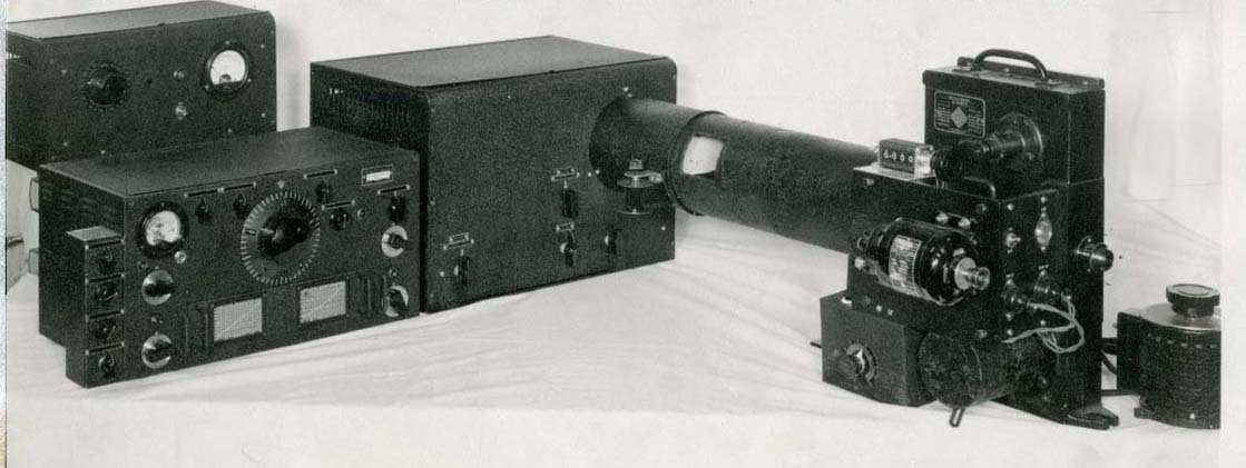 |
| RFP equipment used by OP-20G. Click on image to enlarge.(Extract
from documemt RIP480). |
Although British RFP could distinguish between U-boat and surface
vessel transmissions, British and American RFP gave poor results when a
TINA analysis was performed. The likely cause of this was the consistency
in transmitter hardware (ie emission) and good Morse operator training.
The US Army Signal Intelligence Service (SIS) was another source of
radio intelligence, but their group and OP-20-G were badly hobbled by bureaucracy.
The groups had become rivals, competing with each other to provide their
intelligence data, code named "MAGIC", to high officials. Eventually in
1940, SIS and OP-20-G came to agreement to provide MAGIC on alternating
days, and try to draw up guidelines for which team handled what traffic.
Complicating matters was that the Coast Guard, the FBI, and even the FCC
also had radio intercept operations. The result was that much of the MAGIC
was unused. There was no efficient process for assessing and organizing
the intelligence, or getting it to proper end users.
Domestic US radio intelligence was administered by the Radio Intelligence
Division (RID) but their focus was to track down illegal domestic transmitters
using a network of 58 monitoring stations in the continental US.
Fleet Radio Units (FRU) were the major centers for Allied cryptological
and signals intelligence during the Pacific Campaign of World War II. Initially
two FRUs were established in the Pacific, one at Pearl Harbor, Hawaii,
called Station HYPO or FRUPAC (Fleet Radio Unit, Pacific), and the other,
called Station CAST or Belconnen, at Cavite Naval Yard, then Corregidor,
Philippines. With the fall of the Philippines to Imperial Japanese forces
in April and May 1942, CAST personnel were evacuated to a newly established
FRU at Melbourne, Australia, called FRUMEL (Fleet Radio Unit, Melbourne).
Captain Eric Nave of the Australian Navy, commanded operators
who had been monitoring Japanese preparations for war. He said that
the Japanese Navy had mounted a massive deception exercise to prevent anyone
from realizing that Pearl Harbor was a target. One step which undoubtedly
deceived the US Navy was the transfer of the wireless operators from aircraft
carriers which were to take part in the Pear1 Harbor attack to other ships
in Japan's Inland Sea. Since the Allied intercept operators were using
the fists of their Japanese counterparts to identify the various
enemy radio transmissions, this move completely threw them off guard and
leading them to place the carrier force that was to attack Pearl Harbor
in Japanese home waters.
In 1958, the terms listed below were used to describe various aspects
of radio intelligence. It is not evident at this time as to which other
techniques were applicable to the WWII era other than TINA or RFP.
* Special Identification Technique (SIT) - A collective term including
Morse operator analysis, radio fInger printing. and direction finding.
* Advanced Identification Technique (AIT) - A technique of emitter
identifIcation involving analysis of unintentional variations in amplitude
modulation and frequency modulation which occur in target emissions. This
is the preferred term for ""radio fingerprinting" or "waveform analysis."
* Emitter location/Identification (ELT) - The process of locating or
identifying an emitter through the use of one or a combination of the following
techniques: direction finding, advanced identification techniques, unintentional
frequency deviation. In British usage, the preferred term is
"technical aids."
* Radio Fingerprinting (RFP) -, identify. and classify the unique characteristics
the unique characteristics of individual radio transmitters by the study
of oscillograms of their signals. Also called transmitter identification.
* Morse operator analysis (MOA) - The cataloging and identification
of manual Morse operators by their individual sending characteristics.
Formerly referred to as TINA.
* Morse characteristics analysis (MOCA) - The study and cataloging
of recorded manual Morse transmissions in order to identify individual
Morse operators by their sending operator characteristics.
* TINA - Former term for Morse operator analysis. Derived from the
last four letters of the word "Serpentina", one name for undulator tape
used in early methods of recording hand-send Morse transmissions.
* Direction Finding (DF) - The process determining the apparent
azimuth of an emitter by the use of a direction finder.
* Hull-to-Emitter Correlation (HULTEC) The association of ELINT
intercepts to a specific ship, through analysis of all available parameters
of the intercept and consideration of the elapsed time and possible distance
traveled by the target ship since the signal was last intercepted.
* Unintentional Frequency Deviation (UFD) A technique of emitter identification
involving analysis of unintentional phase variance of on-off keyed Morse
code.
Intelligence Operations in Australia.
Fleet Radio Unit, Melbourne (FRUMEL) was one of two US-Australian-British
signals intelligence units in the Pacific, the other being FRUPAC, feeding
information to US headquarters in Washington.
Nowhere near the size of Britain's famed Bletchley Park intelligence
headquarters, a few hundred people, many from the Women's Royal Australian
Naval Service or female civilians, worked at Monterey, Australia. America
had the biggest units which received intercepts from Mornington in Victoria,
Harmen in Canberra, and Townsville in Queensland. FRUMELs biggest receiving
station was Adelaide River in the Northern Territory, staffed by the US
Navy.
Captain Eric Nave commanded a small Royal Australian Navy cryptographic
unit which worked at Victoria Barracks in Melbourne starting in 1940.
 |
| Members of the Women's Royal Australian Naval Service (WRANS) working
at FRUMEL on Queens Rd, Melbourne in 1942. (Royal Australian Navy photo) |
EQUIPMENT USED FOR RADIO FINGERPRINTING BY THE ROYAL NAVY
The data in the following table was derived from manual M651,
Nomenclature for Radio Equipment Part XXVI dated 1946 This equipment
was used by the British Admiralty and some of it was also issued
to Canada and New Zealand. Minor updates from other sources have
also been applied to this table.
| OUTFIT |
WHERE USED |
MAIN COMPONENTS/COMMENTS |
|
|
|
| REA |
Shore stations for range estimating purposes |
Motor operated camera and receiving panel |
| REB 1 |
Shore recording stations |
Camera, receiver, film viewer, loudspeaker, monitor unit oscilloscope
, power unit. Initially saw service in 1938 |
| REB 2 |
Shore recording stations |
Camera, receiver, film viewer, loudspeaker, monitor, unit, oscilloscope,
power unit. Released in 1940 |
| REB 3 |
Shore receiving stations |
Film viewer, oscilloscope, camera unit, dual beam oscilloscope, B28
receiver, G64 oscillator. REB 3 could be used with different types
of receivers and variable film speeds. Designed primarily for "noise" investigation.
See explanation below table. |
| REB 4 |
Shore recording stations.
Specially approved ships |
This was a modified/improved version of REB 3.
Produced near the end of WWII. Select
this link to view the REB4 Handbook, (Courtesy Collingwood
Heritage Collection). |
| REB 5 |
Under development in 1946 |
|
| REB 6 |
|
No info available at this time. |
| |
|
|
| REC 1 |
Shore recording stations |
Recording unit, M61 amplifier, SE2 rectifier
unit, 12 VDC power unit |
| REC 2 |
Shore recording stations |
Recording unit, M62 amplifier, rectifier unit. |
NOISE INVESTIGATION
This extract, from the British Admiralty document titled "Radio Warfare
1949" provides some details about the technique of noise investigation.
"At the beginning of the war, intercept watch was centered entirely
on radio communications, but with the advent of radar and radio navigational
aids it soon became necessary to organize intercept watches for these
noises
in
order to ascertain progress made by the enemy in using these new features
of radio, and to turn such use, where practicable, to the advantage of
the Allies.
Noise investigation would ultimely ineestigate these types of emissions:
Radar transmissions
Navigational beacons
High speed communications
Radio teleprinter links
IFF Transmissions (Identification Friend or Foe)
Electronic navigational aids
Jamming transmissions
Meteorological balloon transmissions
Guided missile transmissions
The first naval noise investigation was carried out towards the end
of 1940 to determine the characteristics of enemy radar in the Pas de Calais
area of France so that suitable countermeasures could be initiated for
the protection of Allied convoys. At much the same time, assistance was
given to the R.A.F. in elucidating and countering the radio aids used by
enemy bombers over the U.K.
The R.A.F. organization expanded continuously from 1940 onwards, since,
once they had effectively countered the enemy aids over U.K. they were
called on to assist in the Allied bomber offensive over Europe by upsetting
the German radio warning and control systems there.
Naval effort, however, marked time till about 1942, as there were few
important German naval noises to work on. The commencement of large scale
amphibious operations was the next objective . It was soon clear that,
if assaults were to achieve any tactical surprise and avoid crippling damage
from radar controlled coastal batteries, careful pre-investigation of enemy
coastal radar and initiation of suitable counter-measures was essential.
Obviously the problem would become more acute as the Allies got closer
to the heart of enemy resistance, where the German coastal defences
would be stronger.
The problem was not only one of obtaining intelligence to enable jammers
to be designed , but also to provide noise investigation personnel and
equipment to specific ships so that any jammers fitted could he used to
the best advantage . In most amphibious operations noise investigation
equipment and personnel were always in short supply. Towards the end of
the war, a measure of standardization was achieved in the equipment and
personnel supplied to ships,
Meanwhile, the Americans in the Pacific had been faced with a rather
different noise investigation problem. There, distances were great and,
besides amphibious operations, there was more chance of surface engagement
and attacks by enemy naval aircraft. Information was sorely needed about
enemy coastal radar, both for long-range amphibious assaults and for air
strikes on shore targets - particularly to discover 'blind' radar areas
in which forces (both sea and air) could approach undetected. Information
was also needed about enemy ship and airborne radar so that appropriate
countermeasures' equipment could be produced. To obtain this information,
much use was made of specially fitted 'Ferret' aircraft and by including
noise investigation equipment in ships, and especially in submarines operating
in enemy coastal waters, or subject to attack by enemy surface and air
forces. For these reasons, noise investigation developed rapidly in the
U.S. Navy. Their results were communicated freely to the Brits and
steps were in hand at the end of the war to bring the British Pacific
Fleet up to the same standard.
A further use of noise investigation under development at the end of
the war was the tactical possibility of locating enemy radar transmissions
and using this knowledge to evade or to take up an advantageous position;
the value of this depended on the fact that radar transmissions can be
intercepted well outside radar detection range, Naval noise investigation
started ashore but its future would lie mainly afloat and in the
air, since radar ranges are comparatively short and shore stations can
only intercept them when the enemy 'is close at hand.
The Results of Noise Investigation
Practically all successful radar countermeasures were initially due
to noise investigation. The main successes were:-
(i) The countering of the enemy coastal radar chain in the Straits of
Dover; successful jamming of enemy coastal radar in amphibious operations
thus permitting a measure of tactical surprise and subsequent protection
against coastal batteries.
(ii) Masking of feint operations by deliberately inadequate jamming,
so that the enemy should 'see' something but be unable to determine details.
(iii) The general success of the US Navy in the Pacific in countering
enemy radar.
(iv) The countering of enemy radio controlled missiles. "
Researcher Stuart Rayner provides some additional detail about the stations
in the UK which had the capability to analyze
noise.
 |
| This is a Royal Navy REB 6 device fitted into a 1950s era
COMAL (Communications Analysis) bay . The camera and oscilloscope are at
the top left corner of the photo. (Via Collingwood Heritage Collection). |
There are no known photographs of early REB or REC equipment
however Clive Kidd of the Collingwood Heritage collection provides some
elementary descriptions.
"The B40 receiver (a 1950's design), also known as outfit CDW (from
handbook BR222) has two sockets - SK202 and SK203.
These are for REB and REC equipment . REC ( SK202) is the output from the
detector and is an audio output (described as DC) . It was designed
to record audio to a disc, i.e a shellac disc as per the old 78 records
on a piece of kit known as REC. No further info was found on this equipment.
It could also be connected to an audio tape recorder, wire or tape.
SK 203 is connected to REB and is the IF output for "photographic
analysis of transmitter characteristics using equipment with the designation
REB. Manual BR1433 dated 1945 describes REB as being used to "...investigate
the faults and characteristics of any radio transmitter..." The signals
were fed from any receiver (with an IF frequency between "...100
kc/s and 1 Mc/s..." ) into the apparatus and examined visually and also
the signal could be photographed. The apparatus had two CRTs - one for
the operator to sight on and the other covered by a camera. The Y axis
of the CRT was fed with the signal from the receiver, via an adjustable
gain amplifier and the X axis of the operators CRT was fed with a time
base - as per a normal oscilloscope. The only difference between REB and
a scope was REB had two CRTs. The camera could be set to drive the film
past the second CRT at "...1.5/3.8/9.6/24/60/150 cm [yes cm in 1945 in
the Royal Navy ] per sec
] . Time markers could be produced internally
to aid analysis.
The BR on REB does not contain any photos of the kit, only some line
drawings of the chassis and a drawing of an amplitude modulated carrier
signal, in the time domain, to show what a signal might look like - standard
picture as per any text book. There is no description in the BR to aid
in the determination of faults or special characteristics.
I have also found out that there were a number of different marks of
REB equipment - mainly changes to recording speeds and the way the
CRTs were fitted into the case along with other mods to the operator interface".
RANGE ESTIMATION EQUIPMENT (REA)
This was developed by the British during the war as an ancillary to
H/F D/F fixing. It consisted of taking measurements of the path differences
between various incoming rays appertaining to the same signal, and, by
correlating these differences with current ionospheric data, estimating
the distance of the transmitter.
In 1944, after a great deal of experimental work, a method of analyzing
results was evolved which enabled some 80 per cent of experimental intercepts
to be assessed for range with a 10 per cent accuracy. The scheme never
became a practical success as it was complicated and suffered from many
difficulties.
GOING FORWARD
Now lets fast forward to the mid 1960s. Noise investigation and RFP
became a routine function of the Electronic Warfare offices in the ships
of the worlds navies. In 1967, the Royal Canadian Navy developed
an electric "pop-up" radar emitter identification system called the Electrofile
(AN/ULX-501) for the IRE and DDH 280 class of ship. This was the first
form of automation to speed up the process of identifying radar emitters.
It moved the state of the art from operators having to look up possible
emitters in a book (a really slow process) to a rapid presentation of a
list of possible emitters given the frequency, pulse repetition rate and
power level. This system then became the forerunner of today's CANEWS automated
system.
At one time, the most prevalent radar emissions were in the X
band (10 GHz). This very popular frequency was also used by commercial
shipping for navigation. It was therefore a great countermeasures idea
to bury warship navigation /surface radar in amongst all the commercial
ship radars to make identification more difficult. Today, electronic countermeasures
are classified so any RFP operations would still be masked in a cloak of
secrecy.
With the navies of the world discontinuing CW communications mainly
in the 1980s and 1990s, there was no further need for TINA so there is
not much more that can be said about it. RFP, on the other hand,
continues on in its various forms. It is hoped that this research
has been helpful in providing an overview of TINA/RFP operations. Any feedback
about this article can be sent to: jerry.proc@sympatico.ca
It is hoped that this research has been helpful in providing an
overview of TINA/RFP operations.
Contributors and Credits:
1) "A Few Measurements" by John Roscoe, G4QK. Published
in Morsum Magnifact, Autumn 1987 issue
2) Aryeh. Ben-Ami <dufs44(at)bezeqint.net>
3) Frank Barlow ZL2NB Break-In, publication, December
1996.)
4) Clive Kidd <cjckidd(at)waitrose.com> Collingwood
Collection
5) http://www.disarmsecure.org/The%20Origins%20of%20Signals%20Intelligence%20in%20New%20Zealand.pdf
6) http://www.rcsigs.ca/index.php/History_of_Canadian_CESM
7) High Speed Recording of Radiotelegraph Signals by
R. B. Armstrong B.Sc. and J. A. Smale, B.Sc,
8) Radio Warfare document 1949. Ref: SD 1080/47
British Admiralty publication https://www.commsmuseum.com
9) Manual M651, British Admiralty
10) FOIA cases 18871A and 40738B dated June 7,
2006
11) Combined Glossary of Traffic Analytic Terminology,
January 1958
12) Google Books https://books.google.co.il/books?id=EgLBkdfYr5kC&pg=PA6&lpg=PA6&dq=usn+ww2++rfp+tina&source=
bl&ots=dNgDjUmdbX&sig=VvXWb5Ah4tREkq5R6jlEqlGURdw&hl=en&sa=X&redir_esc=y#v=onepage&q=
usn%20ww2%20%20rfp%20tina&f=false
13) https://en.wikipedia.org/wiki/OP-20-G
14) https://en.wikipedia.org/wiki/Fleet_Radio_Unit
15) Captain Nave quote from the book "The Emperors Codes".
16) Daily Telegraph article on Codebreaking http://www.dailytelegraph.com.au/news/codebreakers-at-our-bletchley-park-helped-end-war-in-pacific/n
ews-story/46105ce3db9df95e257a0256fc927604
17) Brian Harrison <briankn4r(at)gmail.com>
18) Nick England <navy.radio(at)gmail.com>
19) Secret Warfare by David Kahn
Back to Table of Contents
June2 22/22