HAIDA's 2nd W/T OFFICE


As more archival material is discovered about the equipment in the 2nd Wireless Office, a picture is beginning to emerge of what was there during HAIDA's WWII days.
1943_2nd_wireless.jpg
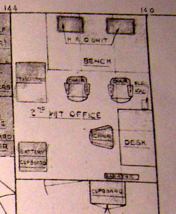
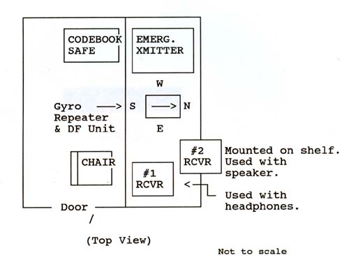
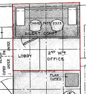
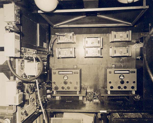
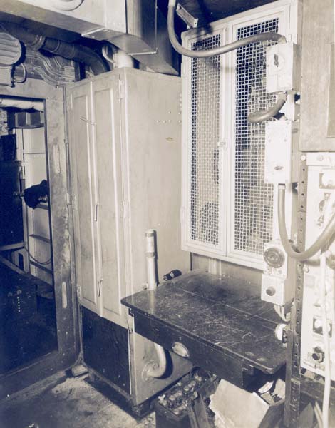
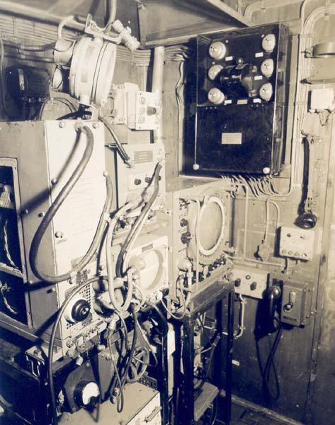
The 2nd Wireless Office was situated between frames 140 and 144. Top of photo is port while the right side is forward. This drawing depicts two National HRO receivers, one 60EM series transmitter plus a battery cabinet. The HRO receivers may not have been fitted and instead British Admiralty receivers were fitted. (Via HMCS HAIDA Library) 
 
2nd W/T OFFICE - RADIO MANIFEST IN 1944
ITEM REFERENCE  SERIAL 
NUMBER
INVENTORY 
DATE
60EM Emergency Tx
Freq Multiplier Unit 4TA
Generator 
AP 4807E
AP W6260
AP 1789
W83
PZ540
MT10605
January 14, 1944
CDC (AC Supply) [1]
CDC (AC Supply) [1]
CDC (AC Supply) [1]
CBB (Battery Supply) [1]
Battery Controller
Coil Box
AP W2835A
AP W2835A
AP W2835A
AP 4046A
AP 4707
AP 4230
MC203515
MC203501
MC203512
PZ167
RP142
RA278
January 14, 1944
FH-3 HFDF  Outfit
B35 Receiver 
DF Attachment 
Goniometer

AP W8126
AP W8150 
AP 5329A

MC201371
MC202512
MC267

January 14, 1944
DHD (Electrical)
Alternator
Generator
Voltage Regulator
Auto Voltage Regulator 
Starter
Voltmeter

AP 8547
AP 1789
AP 5807A
AP W1698
AP 3911
AP W6631

M 1021
MT 10605
9976
33048/534
2113B41
95

January 14, 1944
[1] In reference to the CDC and CBB items, a footnote on the original document indicates these were receivers. CDC were Admiralty B-28's (CR100/4 series) and were bench mounted. CBB was the Admiralty B19 and it was rack mounted. In parenthesis, is the type of power supply used with the receiver.
1943rr2.jpg
This 1943 equipment fitting was drawn from memory by Frank Dobson of Wolfville, N.S in July of 1994. From the available evidence , it looks like the HFDF outfit was part of the 2nd Wireless Office. The outfit was moved during the September/ December 1944 refit to inside the 'new' foremast. As-built, HAIDA's HFDF birdcage antenna was located atop the mainmast  but later moved to the foremast during the same refit. 
Frank provides some additional details about direction finding. "When the U-boat started to send its sighting report, we had to quickly transpose the frequency from the intercept receiver into the HFDF receiver. Correction curves were applied to correct the gyro reading and get a true bearing on the sub.

The ship was calibrated in harbour and Bearing Correction curves produced for the known German frequencies.
There were big variations between the various frequencies and at some points of the compass, the true bearing of the transmitting vessel would be off by and much as 20 to 30 degrees".

FEBRUARY 26, 1946 PHOTOS
During  the September/December 1944 refit, the DF outfit was moved forward, the 291M radar antenna was moved from the foremast to the mainmast and the 291M equipment moved into the 2nd Wireless Office.
1946_2nd_wireless_1749_69.jpg
2nd W/T Office: After bulkhead (left side) - 4TA Transmitter (part of 60 Series transmitter outfit). B28 receivers are on the port bulkhead (dead ahead). The six devices mounted on the port bulkhead are likely plug-in coils for the 4TA transmitter. (RCN photo #HS 1749-69)
1946_2nd_wireless_1749_68.jpg
2nd Wireless Office: Mounted by the aft bulkhead (L-R) is a battery cabinet, battery charging board and part of an Admiralty 4TA transmitter. At the top of the battery cabinet, there is a vent pipe. When the cabinet was removed, a portion of the vent was left attached to the deckhead and it can still be seen today. (RCN photo #HS1749-67)
1946_2nd_wireless_291_hs1749_67.jpg
2nd W/T Office - on forward bulkhead (left side):  291M transmitter; 291M receiver; 291 indicator; aerial control under indicator, power supply board for outfit DUF (under aerial control); PPI; 242 IFF modulator, mixer, transmitter, IFF responser below PPI. 

On starboard bulkhead, (right side):   PPI control bard; 242 IFF control board. (RCN photo #HS 1749-67)

Type 291 was the final British 214 MHz (P-Band) small ship, air search radar that was introduced in 1942. Early versions of this set required separate transmitting and receiving antennas, but a TR (transmit/ receive) box was soon developed. The 291 antenna had a beam width of 40 degrees and was of the lazy 'H' construction. Power output was 100 kilowatts at a pulse length of 1.1 microseconds. It had the capability of detecting a bomber at 15 nm. 
 

Unless otherwise noted, the RCN  photos in the this table came from the collection of the late John Rouey of Ottawa. 


Contributors and Credits

1) John Roue, Ottawa (deceased)
2) Library and Archives Canada file 7400-DDE215-V1 provided by Robert Langille <ewcs(at)ewcs.ca>

Back to Table of Contents
Jan 31/11