 |
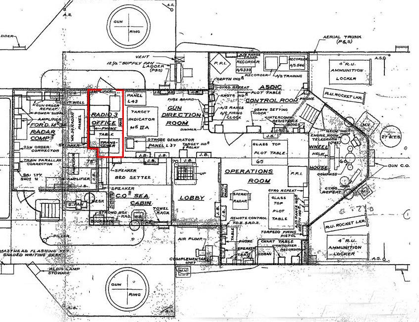
| This 1952 drawing of the flag deck shows the location of Radio 3. It occupies the same space as the former Signalmans table when the Gun Direction Room was called the Signal House on the 1943 drawing. (Drawing courtesy HAIDA Archives) |
LOCATION : Port side, flag deck, below lattice mast.YEAR OF INSTALLATION : 1950. Restored May 26, 1996.
CREW COMPLEMENT : None. This room was normally unmanned and remotely controlled unless frequencies had to be changed and equipment tuned up. Could be locally controlled under emergency conditions.
PURPOSE OF THIS ROOM : It was purely an equipment room and provided four additional UHF circuits.
TELEPHONE CONNECTIONS: Connects with Radio 2 and Message Centre.
HISTORY:
|
| This 1952 drawing of the flag deck shows the location of Radio 3. It occupies the same space as the former Signalmans table when the Gun Direction Room was called the Signal House on the 1943 drawing. (Drawing courtesy HAIDA Archives) |
 |
| Birds eye viiew of Radio 3. |
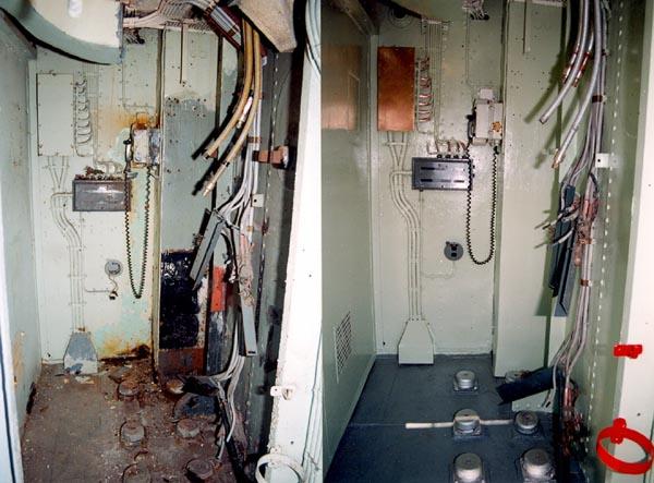 |
| Left - Radio 3 before restoration. A starboard view from the Flag Deck. Right - After restoration in July 1995. The cabinets and equipment still had to be installed. It's a tight fit in this room. There is only about 2 feet between the front of the equipment and the forward bulkhead. |
 |
| The equipment has been put back in place - restoration completed. |
DESCRIPTION OF EQUIPMENT
3.1 - AN/URR-35 Receiver. See description in Radio 1.3.2 - Channel Amplifier Unit. See description in Radio 1.
3.3 - TED3 Transmitter. See description in Radio 1.
There were four AN/URR-35 UHF receivers, four TED3 (AN/URT-502) UHF transmitters and Channel Amplifier Units located in two equipment racks. Mounted over the racks, was a galvanized, sheet metal exhaust vent to carry away the excess heat produced by the equipment.
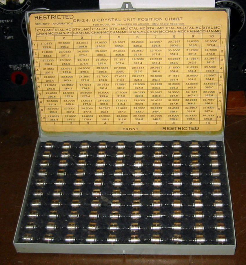
The following standard RCN crystal frequencies were available for the TED3 (AN/URT-502) transmitter. Frequencies marked with an asterisk are for used by CNEL .(Canadian Navy Electrical Laboratories)
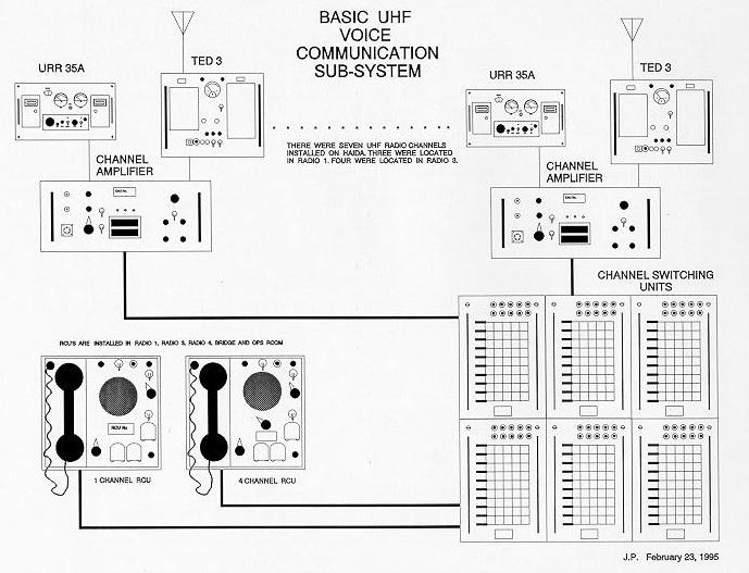
These three pieces of equipment constituted a UHF voice circuit, namely the TED3, the URR-35 and the Channel Amplifier Unit. There were four circuits in Radio 3 and three more in Radio 1 for a total of seven which was the minimum NATO requirement. (Photo by Jerry Proc) The following standard RCN crystal frequencieswere available for the AN/URR-35 receiver.
This is a CR24/U crystal set. The AN/URR-35 receiver and the TED3/URT502 transmitter each had their own kit since the frequency multiplication was different in the transmitter and receiver. (Photo by John Paszkat) DAMAGE TO CRYSTAL HOLDERS - TED-3 TRANSMITTERS
As of result of CR-24/U crystals being damaged due to improper removal ,the RCN issued Fleet Technical Bulletin LE 11/1 dated November 1963.
Damage to crystal holders results when a screwdriver is used as a pry tool in removing crystals from their holders. Such a practice places unnecessary strain on the front section of the sub-assembly resulting in a breakage of the holding fingers. A better method of removing the crystal is as follows:
(a) Open the crystal selector switch door and hold it securely at right angles to the front of the power amplifier sub-chassis.
(b) Ensure that the crystal selector switch is in the position allowing proper alignment of detent mechanism.
(c) Take a positive hold of the crystal using the small end of of a fuse puller.
(d) Withdraw the crystal from its holder exerting a steady pressure pull in a direction parallel to the position of' the crystal holder arms. UNDER NO CIRCUMSTANCES IS ANY OBJECT TO BE USED AS A PRY.
2. To prevent further breakage of' crystal holders caused by inserting oversize crystals, a crystal. gauge (NATO Stock Number 5955-21-460-2668) is supplied jointly' to Naval Supply Depots and HMC Dockyard Workshops for the purpose of' checking for the size of all CR-24/U crystals held by ships.
Signed
J.M. Doull
Commodore, RCN
Director General Sypport Facilities.
UHF System Diagram. Select this link for a PDF version of this drawing. (Drawn by Jerry Proc) 3.4 - AT-150/SRC and AS-390/SRC UHF Antennas
The three TED transmitters and URR-35A receivers in Radio 1 were attached to Model AT-150/SRC dipole antennas which were mounted on the ends of the lower yard arms of the foremast. In Radio 3, the UHF gear which provided four out of the seven UHF channels was attached to Model AS-390/SRC stub antennas which were mounted on the ends of the upper yard arms of the foremast.
Comparisons between the two antennas can be expressed with the following table:
| AT-150/SRC | AS-390/SRC | |
|---|---|---|
| Description | Broadband co-axial dipole antenna | Broadband co-axial stub antenna |
| Frequency range |
|
|
| Nominal Impedance |
|
|
| Polarization |
|
|
| Power Input |
|
|
| Manufacturer |
NY or Bird Electronic |
Cleveland Ohio |
| Alternate Name |
|
|
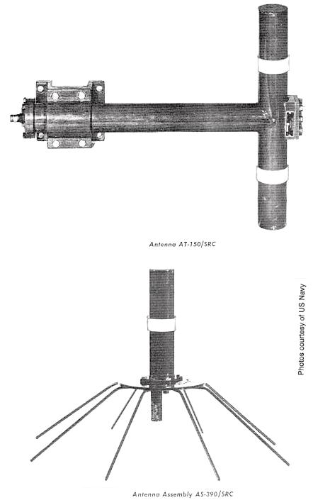 |
| AT-150 and AS-390/SRC UHF antennas |
When at sea and in exercises, at least six, if not all seven, UHF circuits were in use all the time, so there wasn't much opportunity to select which circuit would go to which antenna, except when first setting up before sailing. The radiomen knew which antennas gave the best coverage, and there were many factors that entered into this, including the mast shadow and the radiation pattern of the antenna itself. When time was available, and it seldom was, an aircraft and other ships were employed in order to construct a pattern for each antenna. Given the knowledge that was available to the PO Tel, and the COMMO or OPSO, the most important circuits would be assigned to the best antennas (eg PRITAC, and CIP(P). The antenna with the most suitable pattern would be assigned to the air control circuits such as ASP(P). As the voyage went on, or as the exercise progressed, there would be frequent changes of the COMPLAN, plus equipment breakdowns, so that circuits would get moved around from one transmitter to another, and the best constructed arrangement would soon be sacrificed to expediency. HAIDA was the first ship in the RCN to be fitted with UHF capability.
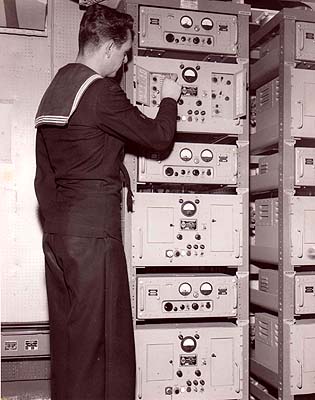 |
| Dave Blais, RCN radioman at the time, adjusts a TED-3 ransmitter in this TED-3/URR-35 installation aboard HMCS Restigouche in 1959. (RCN photo from the collection of Dave Blais) |
A log of Radio 3 restoration activities can be found here.In summary, HAIDA had seven UHF AM only, voice channels. A voice channel was comprised of a AN/URT-502 transmitter, a Channel Amplifier Unit and a AN/URR-35 UHF receiver. Three UHF channels were located in Radio 1 and four channels in Radio 3. The three URTs in Radio 1 were connected to AS-150 antennas fitted on the 'H' shaped yardarm which was affixed to the foremast. The four URTs in Radio 3 were connected to the AS-390 antennas on the 'X' shaped yardarm, foremast. Two of the four AS-390 antennas were always missing and the wind managed to mangle the radials on the remaining two survivors.
Credits and Contributors:1) Dave Blais <brodger0131(at)rogers.com>
May 31//26