 |
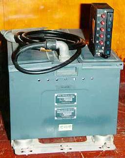
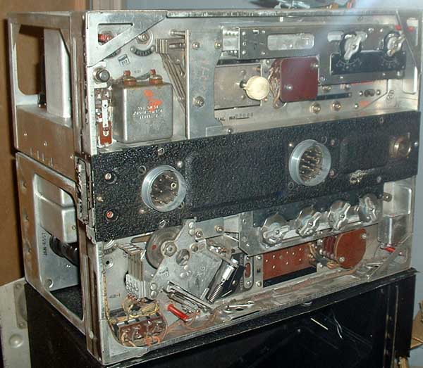
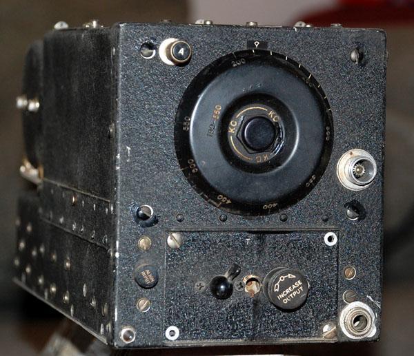
| This is the "Two In Line" HF radio believed to be the HF radio for the Firefly. Not pictured is the control unit. (Photo by Ben Nock, G4BXD) |
This table, prepared by the late Gerry Storey, indicates the electronics suite for each Mark or variant of the Firefly.
| EQUIPMENT | USED ON VARIANT | ||||
| FR I | FR IV | AS 5 | T I | T 2 | |
| HF Radio [1] | TR 5206 | TR 5206 | TR 5206 | Nil | Nil |
| VHF Radio [2] | TR 5043 | TR 5043 | TR 5043 | TR 5043 | TR 5043 |
| ZBX Homer [3] | AN/ARR-2 | AN/ARR-2 | AN/ARR-2 | AN/ARR-2 | AN/ARR-2 |
| IFF | AN/APX-1 | AN/APX-2 | AN/APX-2 | AN/APX-2 | AN/APX-2 |
| Radio Altimeter | AN/APN-1 | AN/APN-1 | AN/APN-1 | Nil (?) [4] | Nil (?) [4] |
| ASH Radar | AN/APS-4 | AN/APS-4 | AN/APS-4 | Nil | Nil |
| Sonobuoys | Nil | Nil [5] | AN/CRT-1A | Nil | Nil |
| Sonobuoy Rx | Nil | Nil [5] | AN/ARR-3 | Nil | Nil |
| NOTES:
[1] The nomenclature TR5206 is presumed to be ARI 5206. See more about this elsewhere in this document. [2] The TR 5043 is commonly known as the SCR 522. One of its four channels was designated as the VHF guard channel for VHF distress at 121.5 MHz. [3] If the ZBX homer was not installed, then a LF radio range receiver (AN/ARC-5 series) would be installed in lieu. This is presumed to be the BC-453/R23. [4] It is unconfirmed if the Trainers had a radio altimeter or not. [5] The RCN leased a dozen Mk IVs from the Royal Navy from 12 February 1948 to 12 January 1949 pending the availability of the Firefly AS 5s. This was an interim measure only. As their designator shows, the IVs were fighter-reconnaissance, not ASW aircraft. Because they were leased, it is rather doubtful if the RCN fitted them with sonobuoy launchers or sonobuoy receivers. |
|||||
FIREFLY ELECTRONICS - DETAILED LISTINGS
| TACTICAL | |
| AN/APS-4 | ASH (Air-Surface Homing) radar. The APS-4 was a light-weight,
pod-mounted airborne search radar which was suitable for either Airborne
Interception (AI) or Air-to-Surface-Vessel (ASV) applications in the X
band. It had the same form factor as a 500 lb bomb and the complete
system weighed 180 pounds. The radar dish can be moved 75 degrees on either
side of centre for air intercept applications and 30 degrees above and
below centre for surface search of vessels or aircraft attacking
from above. The frequency used was 9375 +/-55 MHz. Pulse repetition frequency
adjustable for either 600 or 1000 Hz. The peak RF output power was
35 kw. Made by Western Electric.
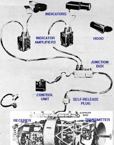
AN/APS-4 system components. (Courtesy Tpub.com) |
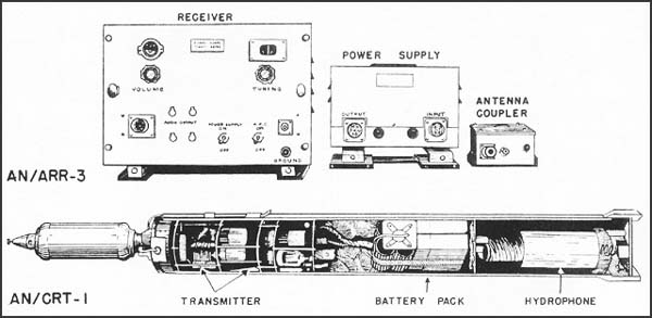
| AN/ARR-3 | Sonobuoy receiver for CRT-1 sonobuoy.
Receiver photo (Courtesy USN Library) |
| AN/CRT-1A | Sonobuoy system. In June 1942, the AN/CRT-1 became the first operational sonobuoy. By 1944, the US Navy had ordered the improved AN/CRT-1A sonobuoys. This was the variant used by the Firefly. |
| AN/APX-1 | IFF Transponder set. Old A-band - 157 to 187 MHz and old G-band - 194
to 212 MHz. Power output 4 to 11watts. Made by Hazeltine. Some major
units of AN/APX-1, AN/APX-1X and AN/APX-2 are identical and interchangeable
System components (Courtesy tpub.com) |
| AN/APX-2 | IFF Mark III airborne combination Interrogator-Responsor-Transpondor manufactured by Stewart-Warner and Bendix. Reliable maximum range for transponders is 90 miles; for interrogators and responsors, 60 miles. |
| COMMUNICATIONS | |
| TR 5206 | HF radio. Believed to be the HF receiver and transmitter components from the ARI 5206 radio system. See more about this radio elsewhere in this document. |
| TR 5043 | VHF Radio. Commonly known as the
SCR-522. The SCR-522 was a voice only, VHF transmitter/receiver operating
in the 100 to 156 Mc bands with a power input of 8 to 9 watts. It was a
re-design of the British TR 1133 VHF set in order that it could be manufactured
with American tooling. Operation was provided on any one of four crystal
controlled channels. Integrally mounted in a common case, was the BC624A
VHF receiver and the BC 625A VHF transmitter. The rest of the system consisted
of 28 VDC input dynamotor (PE-94-A) and various jack and junction boxes.
Input power consumption was 311 watts. Transmitter channel 'D' had the
ability to be used in 'pipsqueak' mode. Pipsqueak was a homing or DF tone
sent from the aircraft to a ground station so the ground station could
take bearings on the aircraft. It was useful either for normal DF work
or when the aircraft was in trouble and the pilot did not want to stay
around to transmit. It is not known if the RCN Firefly used this feature
of the radio.
External view of SCR-522 with remote
control box (Photo by Jerry Proc)
|
| NAVIGATION | |
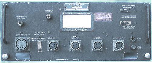
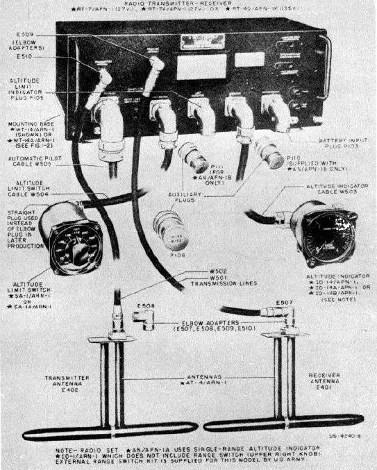
| AN/APN-1 | Radio altimeter; 420-460 MHz, Doppler frequency shift,
dual scale meter 0-400 and 0-4000 feet. Minimum height that can be measured
is 5 feet.
APN-1 Tx/Rx only. (Photo courtesy Kurrajong Radio Museum) APN-1 system components - (Courtesy Tpub.com) |
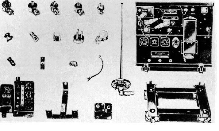
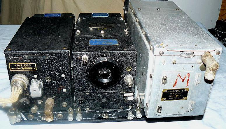
| AN/ARR-2 | ZBX: a VHF homing receiver. The AN/ARR-2 is the combined
version of the AN/ARR-1 (also called the ZB-3) and the BC-946 command set.
The ARR-1 was a small TRF set covering 234-258 MHz, using acorn tubes whose
, output was 800-1000 KHz. This set then connected to the BC-946 which
took the signal and demodulated it to recover a Morse signal. The ARR-2
was a combination of these, in a Command set sized box, which tuned fixed
channels, and used miniature tubes in the front end.
ARR-2 trio. (Photo via Wikipedia) |
| BC-453/R23 | LF radio range receiver. This is assumed to be the R-23 /BC453 receiver
from the ARC-5 series of radios.
R23/BC-453 receiver (Photo by Jerry Proc) |
| OTHER | |
| AK-20 | Camera |
TR 5046 HF RadioIn a document provided by the late Gerry Storey, the Firefly's HF radio is listed as TR 5206. The TR means Transmitter/Receiver and was a British Air Ministry prefix for many radio sets. Through research, it was found that the numeric 5206 was out of range for the Air Ministry TR designators. Two former RAF radio techs have indicated that the radio in the Firefly is the ARI 5206 and not TR 5206. ARI means Aircraft Radio Installation and the 5206 system, first released around 1943, was installed on different aircraft types. The complete equipment group listed for the ARI 5206 at the Kurrajong Radio Museum is as follows:
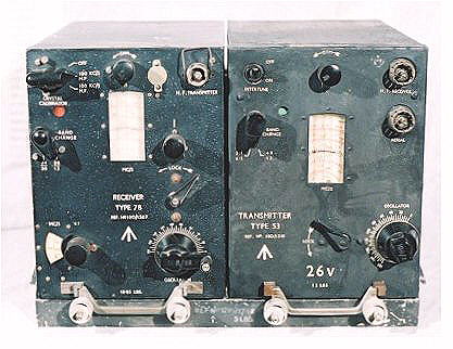
HF receiver Type 78 (2.4 - 13.0 MHz)
HF transmitter Type 53 (2.4 - 13.0 MHz)MF receiver Type 76
MF transmitter Type 51
Modulator unit Type 76
Aerial tuning unit Type 126
Type 260 control unit for any Air Gunners
Type 276 control unit for any ObserversIf all the equipment above was used together, it was known as "Four Square". If only the 78 receiver and 53 transmitter were fitted, it was called "Two in Line". It is now believed that the Two-in-Line system was the one installed in the Firefly.
|
| This is the "Two In Line" HF radio believed to be the HF radio for the Firefly. Not pictured is the control unit. (Photo by Ben Nock, G4BXD) |
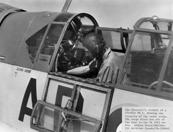 |
| The Observer's cockpit of a Firefly FR I showing the AN/APS-4 radar scope and the TR 5043 VHF radio which is the large box aft of the Observer's seat. (Photo by Andrew Spiro DND/PAC #PA-136660) |
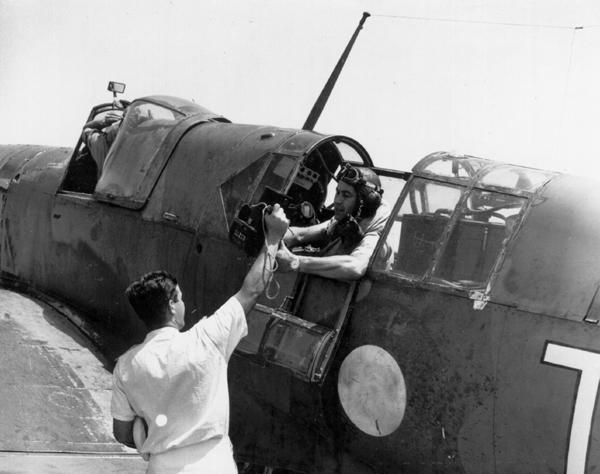 |
| Photographic Officer of HMCS Warrior, Lt. M. Arpin, receives an AK-20 camera in preparation for a photographic mission. (Reid DND/PAC PA-141248) |
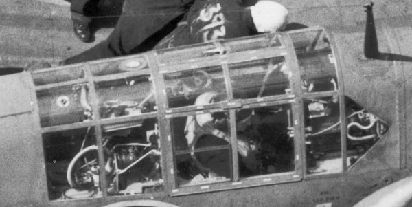 |
| This closeup of an FR I Observer's cockpit does not reveal any easily identifiable electronics. Even the TR5043 VHF radio is not visible behind the Observer. (Part of DND/PAC photo 141231) |
Credits and References:1) Leo Pettipas <lpettip(at)mts.net> Associate Air Force Historian. Air Force Heritage and History 1 Canadian Air Division.
Winnipeg, Manitoba.
2) Peter Cole G3JFS <pseejfs(at)yahoo.co.uk>
3) Ben Nock G4BXD <Military1944(at)aol.com>
4) Louis Meulstee <l.meulstee(at)wxs.nl>
5) AN/APN-1 http://hereford.ampr.org/millist/m2.html
6) Air Ministry radio designations http://home.btconnect.com/gmb/airequip.htm
7) ARI 5206 reference Kurrajong Radio Museum http://www.vk2bv.org/museum/78rx.htm
8) APX-1 reference http://hereford.ampr.org/millist/m3.html
9) Stan Spencer <stan.spencer(at)fullpoint.net>