This new solid-state equipment can operate in two different
modes: either as a Mark 15 receiver or, without any installation modifications
as a Mark 8A. receiver.
For many years, Marks 8 and 8A have been the most widely used airborne
Decca receivers for military applications, and in this context - as in
their extensive civil use - the record has been impressive. The Mark 8
was employed, together with an electromechanical repeater unit, by the
aircraft involved in the nuclear weapon tests at Christmas Island in 1957
and later in Australia. Its more compact derivative, the Mark 8A,
has been widely adopted by the RAF for general navigational purposes. Mark
8A is the principal Decca receiver in use by the United States Army in
Vietnam. The set is still in production and is likely to remain in service
for some years.
Marks 8 and 8A work on the same general principles as the earlier Mark
6 air and Mark 5 marine receivers, and all these sets have in common the
use of valve circuits. More recently a range of solid-state Decca receivers
has been developed, exploiting the increased reliability, reduced size
and weight, lower power consumption and simpler installation (e.g. no forced
cooling) that semiconductor circuits make possible. In addition, the new
sets are improved both in performance and in operational flexibility and
convenience. They permit a large increase in speed capability, to a typical
maximum value of 1800 kt on the baseline. and offer increased protection
against the effects of noise. Operational features include zone identification;
automatic lane setting which internally resolves the ambiguity within the
zone and enables the lane identification meter to be dispensed with and
a 'run/fix' facility which simplifies and relaxes the process of changing
charts. In the new range (Marks 14 to 19), Mark 15 has the features just
mentioned and is the basic design. Mark 14 is a simplified version working
only in the integration mode, 16 and 17 are designed for use with the Omnitrac
computer and 17 incorporates Dectra. Mark 18 is not an airborne set.
Mark 19, the subject of this article, is a dual-purpose set which can
operate in either or both of two different modes. In one mode, the receiver
works as a Mark 15, driving computer Type 1910 and a zone identification
meter and dispensing with lane identification meter and decometers. In
the other, it works as a Mark 8A and can be fitted-with no modification
to an aircraft previously employing a Mark 8A receiver; the new set then
drives the existing decometers, lane identification meter and flight log
computer Type 9360, without any of the cabling or racking having to be
disturbed, and it operates in the same way (albeit with superior performance)
as the receiver it replaces.
In military aircraft which require a flight log pictorial display for
the pilot and a meter display for the navigator, the Mark 19 can work from
a 'Mark 10' chain-in the two modes simultaneously, driving the meters as
a Mark 8A and the flight log as a Mark 15. As well as giving the overall
system a useful degree of redundancy, this frees the pilot from any preoccupation
with lane ambiguity, by virtue of the automatic lane setting, and makes
his chart changes extremely simple with the aid of the run/fix. The navigator
in this combination, and any user of Mark 19, has no action to take on
passing from a Mark 5-type chain to a Mark 10. The receiver senses the
change in lane identification signal and automatically switches the meter
circuits to beat-frequency or multi pulse operation as appropriate. Under
multipulse input, as with the marine Mark 12, the lane identification readings
are reliable at night over a considerably wider area. One of the objects
of Mark 19 is to confer as many as possible of the advantages of the new
receiver techniques upon aircraft that have to be able to use 'Mark 5'
coverage. As another example, it is possible to add a zone identification
meter to an existing Mark 8A installation and drive it from the Mark 19
when within the coverage of a multipulse chain.
The Mark 19 receiver unit is one half of the ATR Short size (4
7/8 x 12 5/8 x 7 5/8 in.) and fits, with an adapter unit, the ATR
Long racking for Mark 8A. The change from 8A to 19 simply involves plugging
in a new antenna amplifier and receiver control-box, both physically identical
with the previous versions - together with the new receiver unit and adapter.
Despite its more densely packed construction, the Mark 19 receiver is several
pounds lighter than Mark 8A. The equipment complies with the environmental
and other provisions of BS.2G-100.
Used as a Mark 8A replacement, Mark 19 can be switched to any one of
10 pre-designated chains in the 63 chain repertoire associated with most
of the new receivers. The limit of 10 is set by the number of conductors
in existing inter unit cabling. In its dual role, i.e. when not part of
an erstwhile Mark 8A installation, anyone of the 63 chain frequencies can
be selected from the control box. When working only as a Mark 15, chain
selection is automatically effected by the wards in the flight log chart
key as in the standard Mark 15 installation.
Mark 19 is certainly the most versatile type of Decca receiver yet designed.
As well as providing the facilities described, it is to be produced in
a version which directly replaces the military Mark 1 (Air) Decca receiver
by the same plug-in method described earlier for Mark 8A. It will also
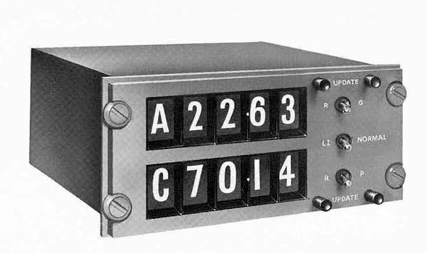
be made available with an alternative type of meter display giving readings
in digital form, for use in certain military aircraft in which space does
not permit the installation of conventional meters, and will be capable
of operating as one of the sensors in a computer based compound navigation
system.